


Chapter 7
7-109
F-7-249
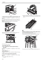
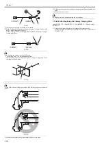
3) Connect the cable [1].
F-7-250
4) Connect the cable to the connector [2] of the potential sensor [1].
5) Attach the potential sensor [1] by reference to the boss [A] of the electrode
for checking potential (FY9-3057-000) [3].
6) Connect the clip [4] for checking the potential sensor to the main body
frame (GND).
F-7-251
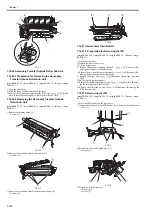
Check to see that potential sensor is attached in an appropriate direction to
the electrode for checking the potential sensor.
F-7-252
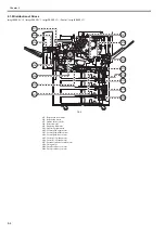
7) After turning ON the main power, set the service mode COPIER > FUNC-
TION > INSTALL > AINR-OFF as '1'.
8) Monitor the fixing upper roller temperature by the service mode COPIER
> DISPLAY > ANALOG > FIX-UC and go through the following oper-
ations depending on conditions:
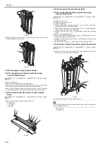
- In case the temperature indicated as 50 deg C or less, place hand on the
shutter assembly [1] when the temperature reaches 145 deg C. Release
hand from the shutter assembly when the drum rotation stops (approx.
20sec).
- In case the temperature indicated as 50 deg C or more, place hand on the
shutter assembly [1] when the temperature reaches 158 deg C. Release
hand from the shutter assembly when the drum rotation stops (approx.
20 sec).
F-7-253
9) Execute the service mode COPIER > FUNCTION > DPC > OFST.
10) Return the value of the service mode COPIER > FUNCTION > IN-
STALL > AINR-OFF as '0'.
11) Turn OFF the main power switch.
12) Attach the potential sensor onto the main body.
7.14.39 ATR Sensor Unit
7.14.39.1 Preparation for Removing the ATR Sensor Unit
0014-2993
imagePRESS C1 P / imagePRESS C1 / imagePRESS C1+ (Printer) / image-
PRESS C1+
1) Open the front cover.
2) Detach the processing unit cover.
3) Lift the hopper unit.
4) Remove the primary charging assembly.
Reference [Re-
moving the Primary Corona Assembly]
5) Remove the pre-transfer charging assembly.
Reference [Re-
moving the pre-transfer corona assembly]
7.14.39.2 Removing the ATR Sensor
0014-2994
imagePRESS C1 P / imagePRESS C1 / imagePRESS C1+ (Printer) / image-
PRESS C1+
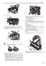
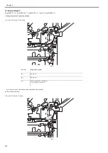
1) Attach the developing assembly cover [1] while holding up the cable [2].
- 1 screw [3]
F-7-254
2) Open the wire saddle [1] and then disconnect the connector [2].
3) The wire saddle [1] is coiled with harness [3] (1 turn). Release the harness
and then disconnect the connector.
[1]
[2]
[1]
[1]
[3]
[4]
[1]
[2]
[A]
[A]
[1]
[3]
[2]
[1]
Summary of Contents for imagePRESS C1
Page 1: ...Oct 22 2008 Service Manual imagePRESS C1 Series ...
Page 2: ......
Page 6: ......
Page 38: ...Contents ...
Page 39: ...Chapter 1 Introduction ...
Page 40: ......
Page 42: ......
Page 72: ...Chapter 1 1 30 F 1 18 ...
Page 85: ...Chapter 1 1 43 T 1 26 ...
Page 88: ......
Page 89: ...Chapter 2 Installation ...
Page 90: ......
Page 94: ......
Page 234: ......
Page 235: ...Chapter 3 Basic Operation ...
Page 236: ......
Page 238: ......
Page 244: ......
Page 245: ...Chapter 4 Main Controller ...
Page 246: ......
Page 248: ......
Page 276: ...Chapter 5 Original Exposure System ...
Page 277: ......
Page 332: ...Chapter 6 Laser Exposure ...
Page 333: ......
Page 342: ...Chapter 6 6 8 F 6 10 1 Laser Light 2 Laser Shutter 3 Laser Shutter Lever 1 1 2 2 1 2 3 3 3 3 ...
Page 344: ...Chapter 7 Image Formation ...
Page 345: ......
Page 431: ...Chapter 7 7 82 ...
Page 462: ...Chapter 8 Pickup Feeding System ...
Page 463: ......
Page 504: ...Chapter 8 8 39 7 F 8 52 8 F 8 53 9 F 8 54 1 3 2 1 2 4 3 1 2 4 3 ...
Page 505: ...Chapter 8 8 40 10 F 8 55 11 F 8 56 12 F 8 57 1 4 2 3 5 4 1 3 2 1 4 2 5 3 ...
Page 506: ...Chapter 8 8 41 13 F 8 58 14 F 8 59 15 F 8 60 5 1 2 3 4 1 2 3 5 4 1 2 3 4 5 ...
Page 507: ...Chapter 8 8 42 16 F 8 61 1 2 3 4 5 ...
Page 509: ...Chapter 8 8 44 3 F 8 64 A Duplexing reversal position 4 F 8 65 2 1 A 2 1 ...
Page 510: ...Chapter 8 8 45 5 F 8 66 6 F 8 67 2 1 2 1 ...
Page 511: ...Chapter 8 8 46 7 F 8 68 8 F 8 69 3 2 1 3 2 1 ...
Page 512: ...Chapter 8 8 47 9 F 8 70 10 F 8 71 3 2 1 2 3 1 ...
Page 513: ...Chapter 8 8 48 11 F 8 72 B Duplexing re pickup stop position 12 F 8 73 3 2 B 1 3 1 2 ...
Page 514: ...Chapter 8 8 49 13 F 8 74 14 F 8 75 1 2 3 1 2 3 ...
Page 516: ...Chapter 8 8 51 F 8 77 SL3 M10 PS17 ...
Page 533: ...Chapter 8 8 68 F 8 154 1 2 4 3 2 3 4 ...
Page 534: ...Chapter 9 Fixing System ...
Page 599: ...Chapter 10 Externals and Controls ...
Page 642: ...Chapter 11 MEAP ...
Page 643: ......
Page 645: ......
Page 695: ...Chapter 12 Maintenance and Inspection ...
Page 696: ......
Page 698: ......
Page 700: ...Chapter 12 12 2 F 12 1 28 9 10 14 13 29 29 11 12 27 6 3 1 2 5 4 7 8 15 16 ...
Page 701: ...Chapter 12 12 3 F 12 2 17 20 24 23 25 26 19 18 24 21 22 ...
Page 704: ...Chapter 12 12 6 F 12 3 1 2 3 4 9 6 5 7 8 11 12 13 14 15 10 ...
Page 715: ...Chapter 12 12 17 F 12 18 1 1 2 2 ...
Page 716: ...Chapter 13 Standards and Adjustments ...
Page 717: ......
Page 719: ......
Page 732: ...Chapter 14 Correcting Faulty Images ...
Page 862: ...Chapter 15 Self Diagnosis ...
Page 894: ...Chapter 16 Service Mode ...
Page 895: ......
Page 1222: ...Chapter 17 Upgrading ...
Page 1223: ......
Page 1225: ......
Page 1256: ...Chapter 17 17 31 F 17 65 2 Turn off the main power switch and remove the USB device ...
Page 1257: ...Chapter 18 Service Tools ...
Page 1262: ......
Page 1263: ......
Page 1264: ...Oct 22 2008 ...
Page 1265: ......


