background image


CHAPTER 3  DISASSEMBLY & REASSEMBLY 

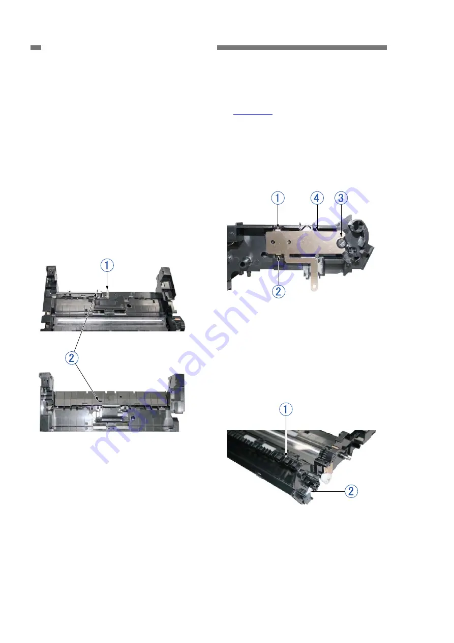
7. Flapper 

‹

  Notes on assembling 

1)  Remove the front unit. 

(Page 3-4)


Install the coil spring 

{

1

 before 

attaching the document pressure plate. 
Attach the fitting part on the left side with 
the pin 

{

2

 on the drive shaft standing 

up, and attach the fitting part on the right 
side while rotating the pulley on the feed 
motor side and slightly tilting the pin so 
that the pin is above the protruding part 
of the document pressure plate. Take 
care to avoid the coil spring shooting off. 
After assembling, check that the 
document pressure plate works properly 
by rotating the pulley right and left. 

2)  Press down on the fitting part 

{

1

 of the 

stop plate from above and unhook it from 
the hole in the base. Then, unhook the 
fitting part 

{

2

 on the opposite side and 

the fitting parts 

{

3

 while moving the stop 

plate slightly to remove the stop plate 

{

4


Figure 3-311 


3) Slide and rotate the flapper 

{

1

 to 

release it from the holes on both sides, 
and then remove it from the base. 

Note:

 Take care to avoid damaging the 

flapper detection switch lever 

{

2

 on 

the right side panel. 


Figure 3-310 

Figure 3-312 


‹

  Notes on assembling 

Insert the fitting parts on the stop plate 
are securely into the holes in the base. 
 

3-12 

COPYRIGHT 

©

 CANON ELECTRONICS INC. 2011              CANON DR-C125 FIRST EDITION


Summary of Contents for imageFormula DR-C125

Page 1: ...SERVICE MANUAL imageFORMULA DR C125 COPYRIGHT 2011 CANON INC CANON imageFORMULA DR C125 Rev 0 PRINTED IN U S A June 1 2011 Rev 0 ...

Page 2: ...COPYRIGHT CANON ELECTRONICS INC 2011 Use of this manual should be strictly supervised to avoid disclosure of confidential information ...

Page 3: ...nance Installation method maintenance method Chapter 5 Troubleshooting Error display and troubleshooting Appendix General diagram etc Information in this manual is subject to change Notification of such changes will be given in Service Information Bulletins Thoroughly read the information contained in this Service Manual and the Service Information Bulletins to gain a correct and deeper understand...

Page 4: ...Roller 3 9 4 Electrical Circuits 2 4 5 Retard Roller Drive Shaft 3 11 5 Timing Chart 2 5 6 Document Pressure Plate 3 11 II READING SYSTEM 2 6 7 Flapper 3 12 1 Reading Unit 2 6 IV READING UNIT 3 13 2 Shading 2 7 1 Reading Unit Front 3 13 III FEED SYSTEM 2 8 2 Reading Holder Front 3 14 1 Feeding Mechanism 2 8 3 Reading Unit Rear 3 14 2 Feed Error Detection 2 11 4 Reading Holder Rear 3 15 IV CONTROL ...

Page 5: ...l Adjust 5 13 11 Firm Load 5 19 12 About 5 20 13 Counter 5 21 14 Machanical Feed Mode 5 22 15 Recovery of Log Files 5 22 III LIST OF FAILURES 5 24 1 Operation Failures 5 24 2 Image Failures 5 24 IV OPERATION TROUBLESHOOTING 5 25 1 Power Does Not Come ON 5 25 2 No Scanner is Found 5 26 3 Scanning Does Not Start 5 26 4 Scanner Does Not Feed Properly 5 27 5 Scanning Speed is Slow 5 28 6 The Eject Loc...

Page 6: ......

Page 7: ...CHAPTER 1 GENERAL DESCRIPTION I PRODUCT OUTLINE 1 1 II NAME OF PARTS 1 6 III USER OPERATION 1 7 COPYRIGHT CANON ELECTRONICS INC 2011 CANON DR C125 FIRST EDITION ...

Page 8: ......

Page 9: ...Document Face up feeding Real direction setting for document None of up side down as setting 5 Scanning speed A4 200dpi 25ppm 50ipm at B W gray and color modes 6 Automatic image processing Auto color detection and Auto resolution modes Full auto mode 2 modes above Auto size Deskew Blank skipping and Text Orientation 7 Hybrid OS Both Windows and Mac OS are supported Windows is a trademark of Micros...

Page 10: ...0 sheets A4 Replace parts if necessary 8 Installation By user 9 Option 1 Flat bed scanner FSU 101 10 Consumable parts Commercial goods 1 Exchange Roller Kit Feed roller and Retard roller Replaced by user Expected life is 100 000 sheets 11 Bundle software 1 ISIS TWAIN driver CaptureOnTouch 2 Others depend on Sales region 12 Sensor type Density 1 line 3 parallel CMOS contact image sensor 600dpi 13 S...

Page 11: ... settings and other conditions 22 Document feed path U turn path and straight path Manual selection is available 23 Document size 1 Width 50 8 to 216mm 2 Length 53 9 to 355 6mm Length 297mm more should be 1 sheet feeding 70mm less should be fed with straight path 24 Document weight Thickness 1 U turn path 52 to 128g m2 0 06 to 0 15mm 2 Straight path 40 to 209g m2 0 05 to 0 25mm 25 Special document...

Page 12: ...ations 28 Operation Indication 1 Power button with LED 2 Start button 3 Eject selection lever 4 Feed selection lever 5 OPEN button Table 1 101c External dimensions mm Figure 1 101 1 4 COPYRIGHT CANON ELECTRONICS INC 2011 CANON DR C125 FIRST EDITION ...

Page 13: ... extraordinary noise smoke heat and odor occur immediately unplug the power cord 6 Disposal Follow local regulations when disposing of the product and parts This product is subject to the WEEE Directive in Europe Be careful not to get clothing ties long hair etc caught in this machine as it may cause injury Should this occur immediately unplug the power cord Do not insert fingers in the feed secti...

Page 14: ...button 5 Feed selection indicator 6 Feed selection lever 7 Feed extension plates 8 Eject support 9 Feed support 10 Document feed tray 11 Connectors 12 Eject selection lever Connectors Rear View Figure 1 203 Figure 1 204 1 Power connector 2 USB connector 1 OPEN button 2 Kensington slot 1 6 COPYRIGHT CANON ELECTRONICS INC 2011 CANON DR C125 FIRST EDITION ...

Page 15: ... other operations refer to the User Manual for this machine For installation and maintenance refer to CHAPTER 4 INSTALLATION MAINTENANCE 1 Placing Documents 1 Open the document feed tray and extend the feed extension plates and eject support to suit the document Figure 1 301 Figure 1 302 Figure 1 303 Figure 1 304 COPYRIGHT CANON ELECTRONICS INC 2011 CANON DR C125 FIRST EDITION 1 7 ...

Page 16: ...age separation and U turn eject Figure 1 305 Figure 1 306 3 Place the document and adjust the document guides to fit the document width Note In this example the document is placed with the writing facing you and the top of the document at the top Figure 1 307 1 8 COPYRIGHT CANON ELECTRONICS INC 2011 CANON DR C125 FIRST EDITION ...

Page 17: ...nTouch Figure 1 308 2 When the main screen is displayed click Scan First Note Since Scan First is enabled by default this operation is not required Figure 1 309 3 Change the Enable continuous scanning and Scans in the full auto mode settings as needed Note In this example set Enable continuous scanning OFF and Scans in the full auto mode ON Figure 1 310 4 Click the Start button to start the scan F...

Page 18: ... the output method Figure 1 313 7 When the output is complete the finished screen is displayed Figure 1 314 Reference Scanner Settings Screen You can display the settings on the screen by setting Scans in the full auto mode OFF in the step 3 You can then open the advanced settings dialog box by setting Use advanced settings dialog box ON and clicking the button on the right Figure 1 315 Figure 1 3...

Page 19: ...Jams 1 Remove any remaining documents from the document feed tray Figure 1 317 2 Press the OPEN button and open the front unit out towards you Remove any jammed documents Figure 1 318 Figure 1 319 3 If the document is jammed in the eject side open the eject pocket Remove any jammed documents Figure 1 320 Figure 1 321 ...

Page 20: ......

Page 21: ...UTLINE 2 1 II READING SYSTEM 2 6 III FEED SYSTEM 2 8 IV CONTROL SYSTEM 2 13 V POWER SUPPLY 2 17 VI LAYOUT OF ELECTRICAL COMPONENTS 2 18 VII PARTS LAYOUT ON EACH PCB 2 19 COPYRIGHT CANON ELECTRONICS INC 2011 CANON DR C125 FIRST EDITION ...

Page 22: ......

Page 23: ...This system performs from document pickup to document ejection 3 Control system This system is comprised of an image processing section and a feed control section The image processing section controls the reading system and processes the read image data The computer also processes image data The feed control section controls the feed system 4 Power supply section This section supplies DC power con...

Page 24: ...ler 2 Retard roller 3 Registration roller drive 4 Registration roller follower 5 Eject roller drive 6 Eject roller follower 7 U turn eject roller drive 8 U turn eject roller follower 9 Document pressure plate 10 Flapper 11 Reading unit front 12 Reading unit rear 2 2 COPYRIGHT CANON ELECTRONICS INC 2011 CANON DR C125 FIRST EDITION ...

Page 25: ...mit to the retard roller Also the document pressure plate of the pickup section is also moved up and down by the feed motor Control PCB Feed motor Feed selection lever Torque limiter One way clutch Main motor Retard roller Feed roller Registration roller Eject roller U turn eject roller Figure 2 103 COPYRIGHT CANON ELECTRONICS INC 2011 CANON DR C125 FIRST EDITION 2 3 ...

Page 26: ...ctrical circuits block diagram of this machine is shown below Reading unit front Reading unit rear Front unit PCB Control PCB Main motor Feed motor Sensor Sensor Switch AC adapter Flapper switch Figure 2 104 2 4 COPYRIGHT CANON ELECTRONICS INC 2011 CANON DR C125 FIRST EDITION ...

Page 27: ...s shown below Once the machine starts scanning it activates the feed motor and the main motor to feed the document Start End Note indicates the feeding state at the maximum speed Document sensor Registration sensor Feed motor Main motor Reading front side Reading rear side Figure 2 105 COPYRIGHT CANON ELECTRONICS INC 2011 CANON DR C125 FIRST EDITION 2 5 ...

Page 28: ...eference sheet are mounted on the holder Photosensitive pixels are mounted on the CIS PCB with a density of 600 dpi in a line The effective reading width is 216 mm and the number of effective picture elements is 5107 A set of three basic color LEDs red green and blue RGB is mounted only on the one side This single side illumination causes a shadow on a document which may effect on the image data q...

Page 29: ...is reflected from the white reference sheet on the upper unit to be input to the sensor on the CIS PCB Since the white reference sheet is placed under the reading glass feeding document does not cause dirt on it Note that executing shading while the reading glass is dirty can cause poor images such as white lines occurring in the images When this machine is turned ON or starts scanning it reads th...

Page 30: ... Registration roller follower 5 Eject roller drive 6 Eject roller follower 7 U turn eject roller drive 8 U turn eject roller follower 9 Document pressure plate 10 Flapper 11 Reading unit front 12 Reading unit rear 13 Document sensor detection point 14 Ultrasonic sensor detection point 15 Registration sensor detection point 2 8 COPYRIGHT CANON ELECTRONICS INC 2011 CANON DR C125 FIRST EDITION ...

Page 31: ... Feed The following shows a cross sectional diagram of the feed unit before starting the feed The document pressure plate is in the lowered position When a document is placed in the feed slot the edge of the document lines up at the end plate When a scan is started the document platen moves and the document begins to feed by being pressed against the feed roller Misfeeds and double feeds have been...

Page 32: ...ree and the separation function becomes invalid To provide space between the trailing edge of a document and the leading edge of the next document the drive speed of the feed roller is slightly lower than the drive speed of the registration roller and eject roller If it is left as it is the document is braked when it touches the feed roller and the registration roller and therefore a one way clutc...

Page 33: ...the specified time after the machine starts scanning a U turn path b Early Reach Jam The leading edge of the following document was detected after the trailing edge of the document was detected by the registration sensor before the document has been fed for a specified length c Residual Jam The trailing edge of the document was not detected even though the document has been fed for the maximum spe...

Page 34: ...el When overlapping documents are fed the signal level is different from when properly feeding a single document This machine interprets this difference as a double feed Note that since this level of difference occurs depending on the presence of a layer of air a double feed will not be detected if the document is tightly adhered by static electricity or adhesive Furthermore double feed is judged ...

Page 35: ...puter USB interface Controller PCB Analog preprocessor Scanner controller Ultrasonic control microcontroller Ultrasonic sensor receiver Front unit PCB Ultrasonic sensor transmitter Document sensor transmitter Switch power Switch scan Door sensor Power LED Motor driver Motor driver Main motor Feed motor Registration sensor Document sensor receiver Figure 2 401 COPYRIGHT CANON ELECTRONICS INC 2011 C...

Page 36: ...tores each setting IC115 SD RAM Memory Saves image data temporarily and serves as a work memory for the Scanner Controller IC117 NOR Flash Memory Stores firmware IC19 Motor driver Drives the main motor IC20 Motor driver Drives the feed motor IC23 Ultrasonic Control Microcontroller Controls transmission and reception of ultrasonic waves and double feed detection Table 2 401 2 14 COPYRIGHT CANON ELE...

Page 37: ...fset adjustment Gain adjustment A D conversion Scanner controller LED light control 10 bit 8 bit Color Colorcorrection three dimensional Bleed through reduction when on One dimensional gamma correction Edge enhancement Binarization Binary Data after image processing Other processing Auto size detection Deskew Image rotation Skip blanks File creation Other Grayscale Color Grayscale Figure 2 402 COP...

Page 38: ...ustment and A D conversion Analog signals are converted into 10 bit digital signals in the analog processor Then the image data is transferred to the scanner controller and converted from 10 bits to 8 bits After that the image data is output to the computer through the USB interface The computer performs the shading correction and the image processing according to the user settings Since this mach...

Page 39: ...onents When no documents have been fed or there has been no communication via this USB I F for an extended period of time the machine enters the sleep mode Energy Star mode When the machine is in the sleep mode the electrical circuits enter a sleeping state However the CPU does not enter a sleeping state This machine automatically returns from the sleep mode when it receives communication from a c...

Page 40: ...ter Front unit PCB LED803 Registration sensor Control PCB Q300 LED301 Ultrasonic sensor receiver Control PCB SR1 Ultrasonic sensor transmitter Front unit PCB SR800 Door sensor Front unit PCB PS801 Sensor Flapper switch Base unit right SW301 Feed motor Base unit left M301 Monitor Main motor Base unit right M302 Table 2 601 2 18 COPYRIGHT CANON ELECTRONICS INC 2011 CANON DR C125 FIRST EDITION ...

Page 41: ...itch J306 USB interface J309 4P Feed motor J310 4P Main motor J601 15P CIS PCB front J602 15P CIS PCB rear Table 2 701 Symbol Details LED101 Blinks CPU operation normal LED301 Registration sensor transmitter Q300 Registration sensor receiver Q301 Document sensor receiver SR1 Ultrasonic sensor receiver Table 2 702 COPYRIGHT CANON ELECTRONICS INC 2011 CANON DR C125 FIRST EDITION 2 19 ...

Page 42: ...J801 11P Control PCB Table 2 703 Symbol Details LED800 Front Power indicator LED803 Rear Document Sensor transmitter PS801 Rear Door Sensor SR800 Rear Ultrasonic sensor transmitter SW800 Power switch SW801 Start switch Table 2 704 2 20 COPYRIGHT CANON ELECTRONICS INC 2011 CANON DR C125 FIRST EDITION ...

Page 43: ...RTS 3 1 II FRONT UNIT 3 5 III BASE UNIT 3 8 IV READING UNIT 3 13 The machine shown in the photographs of the figures in this chapter may be different from some mass produced machines COPYRIGHT CANON ELECTRONICS INC 2011 CANON DR C125 FIRST EDITION ...

Page 44: ......

Page 45: ...ol You should unhook the rear and bottom fitting parts first Figure 3 101 Note Once you have removed the left cover the cable cover 1 and front unit 2 can be removed Take care to avoid accidentally dropping or damaging it Figure 3 102 Notes on assembling Attach the cable cover so that the cable would not be caught in parts Then insert the cable through the cut out 1 in the left cover and attach th...

Page 46: ...ght cover 2 Note Take care to avoid scratching the cover with the tool You should unhook the rear and bottom fitting parts first Figure 3 105 Notes on assembling Ensure that you attached the door sensor lever on the base side correctly After attaching the eject selection lever to the cover attach the cover Ensure that you align the positions of the fitting parts on the eject selection lever and fl...

Page 47: ...guides unhook one side of the fitting part 2 and then remove the document feed tray Figure 3 106 3 Use a tool to unhook the 4 pairs of fitting parts 1 2 each on the upper plate and remove the rear cover 2 Figure 3 108 4 Bend the document feed tray 1 with attached extension plates and cover 2 to unhook the fitting part 3 inside and then slide in the direction of the arrow to separate Figure 3 109 N...

Page 48: ...2 connectors 2 and remove the 3 flat cables 3 each internal wire is copper foil from the cable guide of the main body Figure 3 110 4 Open the front unit 1 remove the shaft 2 from the left side then unhook the fitting part to pull the shaft out from the opposite side and remove the front unit Figure 3 111 3 4 COPYRIGHT CANON ELECTRONICS INC 2011 CANON DR C125 FIRST EDITION ...

Page 49: ...itting parts by pulling it out 2 Front Cover 1 Remove the front unit Page 3 4 2 Remove the eject pocket Page 3 5 3 Use a tool to unhook the 10 pairs of fitting parts 1 in sequence to spread open the gap and then remove the front cover 2 Note Take care to avoid scratching the cover with the tool You should unhook the bottom fitting part first Figure 3 202 Note Once you have removed the front cover ...

Page 50: ... back side of the PCB Figure 3 203 Notes on assembling In order to prevent the internal cables from becoming pinched during assembly ensure that they do not protrude from the cable guide align the positions of the front cover and the joint part on the main body side and push them together There should not be any gap Figure 3 204 Notes on assembling Mount the front unit PCB before attaching the ope...

Page 51: ...age 3 4 2 Remove the front cover Page 3 5 1 Open the front unit spread open the fitting parts 1 on both sides and then remove the follower roller 2 3 Spread open the fitting part 1 and remove the feed roller drive shaft 2 Note In the below figure the roller in the registration side is removed Figure 3 205 Figure 3 206 COPYRIGHT CANON ELECTRONICS INC 2011 CANON DR C125 FIRST EDITION 3 7 ...

Page 52: ...diagram for determining the position place it into the holes on the PCB Do not forget to tighten the screws for the USB connector 2 Feed Motor 1 Remove the left and right covers Page 3 1 Page 3 2 2 Remove the rear cover Page 3 3 3 Remove the connector 1 and 2 screws 2 TP tapping M3 and then remove the feed motor 3 Note Once you have removed the motor the timing belt pulley and gear can also be rem...

Page 53: ...r Page 3 8 Page 3 9 Remove any other cables connected to the control PCB Note Once you have removed the motor the timing belt can also be removed The motor is attached with the mounting plate Do not remove the mounting plate Figure 3 304 4 Remove the screw 1 BH M3 and the coil spring 2 on the back side Then remove the mounting plate with attached PCB 4 while ensuring that it does not touch the lig...

Page 54: ...ponent Once you have removed the pulley the detection lever 3 can also be removed Notes on assembling Push the bearing of the roller all the way in and fit together the fitting part Insert the roller shaft all the way into the end by aligning the shape of the roller shaft with the hole in the pulley Before attaching the mounting plate you should check that the light guide for the registration sens...

Page 55: ...and the pulley of the registration side drive roller Note Refer to 4 Drive Roller Page 3 9 5 Spread open the fitting part 1 and remove the retard roller drive shaft 2 Note Since the protrusion of the fitting part on the right side is smaller than on the left side you should remove it from the right side Once you have removed the document pressure plate the inside coil spring can also be removed No...

Page 56: ...document pressure plate works properly by rotating the pulley right and left 2 Press down on the fitting part 1 of the stop plate from above and unhook it from the hole in the base Then unhook the fitting part 2 on the opposite side and the fitting parts 3 while moving the stop plate slightly to remove the stop plate 4 Figure 3 311 3 Slide and rotate the flapper 1 to release it from the holes on b...

Page 57: ...ing parts 1 on both sides and then pull the reading unit front 2 out Note Do not pull it excessively because the cable is connected to it Figure 3 401 2 Remove the cable 1 FFC from the connector Figure 3 402 Notes on assembling Connect the cable and then push the cable inside before pushing in the reading unit COPYRIGHT CANON ELECTRONICS INC 2011 CANON DR C125 FIRST EDITION 3 13 ...

Page 58: ...oking the fitting parts Once you have removed the case the CIS unit can also be removed so hold it to avoid dropping it Figure 3 403 Notes on assembling Push until all of the fitting parts are securely fastened There should not be any raised parts and gaps 3 Reading Unit Rear Note The reading units front and rear have different holder shapes 1 Open the front unit insert a tool with a thin leading ...

Page 59: ...to prevent dust from getting inside Furthermore take care to avoid touching the inner side of the glass and the surface of the lens array 1 Remove the reading unit rear 2 Place the reading holder 1 at the bottom and unhook the 8 pairs of fitting parts 2 4x2 using a tool with a thin flat tip to remove the case 3 Then remove the CIS unit from the reading holder 1 Note Be careful not to damage the ho...

Page 60: ......

Page 61: ...CHAPTER 4 INSTALLATION MAINTENANCE I INSTALLATION 4 1 II PARTS TO BE REPLACED 4 4 III MAINTENANCE 4 6 COPYRIGHT CANON ELECTRONICS INC 2011 CANON DR C125 FIRST EDITION ...

Page 62: ......

Page 63: ...ce USB interface Hi speed USB 2 0 Monitor Resolution 1024 x 768 XGA or higher Optical drive Able to read DVDs 2 OS Microsoft Windows XP Microsoft Windows XP x64 Edition Microsoft Windows Vista 32 64 bit edition Microsoft Windows 7 32 64 bit edition Mac OS X Note For details on each version refer to the user manual 2 Checking the Accessories Open the package and take out the main body and its acces...

Page 64: ...ould be installed before connecting the machine to a computer The following shows an outline of the installation on Windows Figure 4 101 1 Login using an account with Administrator privileges 2 Before installing the software exit all other applications 3 Load the setup disk into the DVD drive of the computer 4 The setup menu starts automatically 5 Click Typical Installation Figure 4 102 Figure 4 1...

Page 65: ...connector on the main body and connect the power cord to the outlet 1 Press the power button The power button lights when the power turns ON 3 Check that the power switch of the machine is off Of the power is on turn it off Power button 4 Connect the machine and the computer using the included USB cable Figure 4 105 The preparation is now complete Check whether scanning is really performed Refer t...

Page 66: ...Remarks 1 Feed roller MA2 9416 000 2 Retard roller MA2 7326 020 100 000 sheets Because of the worn rollers it is necessary to replace when the feed error are occurred after cleaning Note The items above are assigned as service parts and an exchange roller kit is assigned as commercially available products for a set Table 4 201 2 Replaced by service technicians None 4 4 COPYRIGHT CANON ELECTRONICS ...

Page 67: ...CB MG1 4588 000 1 3 Reading Unit front MG1 8311 000 1 4 Reading Unit rear MG1 8310 000 1 Includes reading holder 5 Reading Holder front MF1 4715 000 1 A reading glass attached 6 Reading Holder rear MF1 4714 000 1 A reading glass attached 7 Feed motor MG1 4639 000 1 8 Main motor MG1 4586 000 1 9 AC adapter MG1 4578 000 1 Outside of China 10 AC adapter China MG1 4579 000 1 China only Table 4 202 COP...

Page 68: ... clean and dry cloth to wipe off any dirt 3 Retard roller z 4 Feed roller z 5 Other rollers Use a cloth slightly dampened with water and well wrung out to remove any dirt and then use a clean dry cloth to wipe the main body Note Remove the retard feed roller from the main body before cleaning 6 Feed path Use such as air blowers to remove any dust and paper particles that have accumulated on the fe...

Page 69: ...4 304 Figure 4 305 Feed roller When attaching the roller align the cut out section of the roller with the axle Figure 4 306 Figure 4 307 5 Resetting after replacement The counters need to be reset after replacing the rollers The following shows the method for doing this in Windows Start Windows and login with administrator privileges Click the Start button on the computer and then click All Progra...

Page 70: ...cians is specified However when visiting a user check whether the reading glasses and the rollers are dirty If they are very dirty instruct the user to follow the user maintenance procedures Recommend the user to replace consumable parts if necessary Furthermore remove the cover check that there is no paper dust or other foreign matter inside the main body and then perform cleaning 4 8 COPYRIGHT C...

Page 71: ...G I ERROR DISPLAY 5 1 II SERVICE MODE 5 2 III LIST OF FAILURES 5 24 IV OPERATION TROUBLESHOOTING 5 25 V IMAGE TROUBLESHOOTING 5 29 VI AFTER REPLACING PARTS 5 34 COPYRIGHT CANON ELECTRONICS INC 2011 CANON DR C125 FIRST EDITION ...

Page 72: ......

Page 73: ...tton flashes Power button Figure 5 101 2 Computers Error messages are displayed on the screen of the computer connected to the machine Each of the different pieces of software applications drivers OSs have their own unique messages which they control There are many user related messages such as when the user performs an incorrect operation Users should resolve problems according to the error messa...

Page 74: ...e mode starts from this screen A list of the modes is show below No Button displayed description 1 All Adjustment Performs all adjustments of the following No 2 4 relating to image reading 2 Registration Adjustment Performs the registration adjustment 3 Light Adjustment Performs fine adjustments to the shading correction value 4 Document Sensor Adjustment Fixes the initial value of the amount of l...

Page 75: ...hine and also install the CaptureOnTouch as necessary Please refer to the User Manual on installation of them However when checking a specification such as the scanning speed the system requirements for a computer described in the User Manual should be satisfied Note Keep the name of the folder and the password confidential from the user 3 How to Start and Finish How to start 1 Start the computer ...

Page 76: ...er replacing or reassembling the reading unit or the registration detection related part or after replacing the control PCB recording the adjustment data This mode and the other adjustment items can be performed at the same time For details refer to the All Adjustment item Adjustment sheet The dedicated sheet is required to execute this mode However you can create the sheet by drawing a black line...

Page 77: ... LTR size paper due to the computer specifications set to half the size Note that you should cut that paper perfectly straight without any slant Operation Procedure 1 Clean feed path roller and reading glass 2 Place a piece of the registration adjustment sheet you prepared Make sure to set the document guides to fit the sheet to prevent skews Note The black edge needs to be detected as the leading...

Page 78: ... data Figure 5 207 This mode and the other adjustment items can be performed at the same time For details refer to the All Adjustment item 5 The sheet is fed After the adjustment is complete the progress screen disappears and the screen returns to the service screen Adjustment sheet The shading sheet is required to execute this mode Use TKM 0326 or TKM 0332 which is the same shading sheet as the o...

Page 79: ... Figure 5 210 5 Even after the sheet has been ejected the data may be processed inside the machine The progress screen disappears and a warning screen is displayed Do not turn OFF the machine or perform any operations until the warning screen disappears Figure 5 208 3 On the service screen select Light Adjustment Figure 5 211 6 After the adjustment is complete the warning screen disappears Figure ...

Page 80: ...e factory is set when the sensor is shipped from the factory but the adjustment is carried out if the document sensor does not detect a document correctly because the ambient amount of light is very different and so on Also run this mode after replacing the control PCB on which data is stored This mode can be executed together with other adjustment items For details refer to the All Adjustment ite...

Page 81: ...djustment sheet is the same 219 mm as that of the shading sheet to prevent skews Figure 5 214 4 The adjustment starts automatically The sheets are fed and the progress screen is displayed Note Two shading sheets with a black line for registration adjustment may be used Operation Procedure 1 Clean feed path roller and reading glass 2 Open the document guides fully extended then place a prepared reg...

Page 82: ...ion screen is displayed This mode checks operations of each hardware inside of the machine Basic screen 1 On the service screen select Dcon Check Figure 5 216 6 Finally Document Sensor Adjustment is executed After the adjustment is complete the completion screen is displayed Click OK Figure 5 218 2 The DCON Check screen is displayed Select a menu to execute on this screen Figure 5 217 Figure 5 219...

Page 83: ...rs when the Start button is pressed Door sensor This icon appears when the front unit is open Registration sensor This icon appears when the registration sensor detects paper Note Document sensor This icon appears when the document sensor detects paper Note Flapper switch The icon appears when the flapper is set to straight eject When the corresponding LED button is selected the LED lights Make su...

Page 84: ...ns on the document lamp in red Placing overlapping paper on the sensor turns on the two double feed lamps in red The screen when double feeding is detected is shown below The current analog value of the document sensor is displayed Although this is not normally used in the market it allows data to be provided for design inspection If you have changed this value by mistake execute Document Sensor A...

Page 85: ... should also be executed after replacing the control PCB that records the adjustment data On the service screen select Check Device to display the Check Device screen Basic screen On the service screen click Manual Adjust to display the Scaling Control screen Figure 5 226 MAIN Main body firmware DFD SUB Ultrasonic sensor Note Version of the main body firmware can also be confirmed on the user s dr...

Page 86: ...ged by directly entering in the data box or by using the scroll arrows Units are mm and the setting range is 5 0 The direction delays the timing For example if set to On 1 0 1mm of the leading edge of the image is cut off Note In this machine only On is used for adjustment And more than 2 mm in the minus direction for On is invalid No Details 4 Set Reset Set Sets the changed values Reset Returns t...

Page 87: ...ure 1 The Scanning Control screen is displayed 2 Place a single adjustment sheet and align the document guides You should place the sheet with the patterned face towards you and the leading edge at the bottom inside the machine Figure 5 231 3 Set the resolution and size and then click the Scan button 6 Check the trailing edge image next and set the adjustment values For example if you want to exte...

Page 88: ...ration Adjustment The function of the Registration Adjustment button is the same as section 4 Registration Adjustment and is linked to the setting value Place the registration adjustment sheet and then click this button The set values are then displayed 2 0mm Figure 5 232 7 Place the adjustment sheet and scan again Check the displayed image Figure 5 234 Note Repeat the procedure again if the adjus...

Page 89: ...r by using the scroll arrows This additional change value is added to the value previously set by the automatic adjustment For example if the value is already 0 1 enter 0 9 if you want to add 1mm or enter 1 1 if you want to subtract 1mm 4 After entering the values click the Set button 5 Scan the image again and check the position Figure 5 236 d Procedure after replacing the control PCB This sectio...

Page 90: ...ment section 2 Execute automatic registration adjustment For details refer to the Automatic Registration Adjustment section 4 Check the trailing edge of the image and set the scale parameter adjustment values Note that these are the Factory Scale Parameter values For more details refer to the Scale Parameter Adjustment section 3 Next perform the procedure from Step 2 in the previous section Withou...

Page 91: ...rm Load 2 The screen is displayed requiring the file in which software is stored to be selected 3 Select and open the file 4 It is loaded automatically and a progress screen is displayed Figure 5 240 5 When the load is finished the progress screen disappears and the service screen returns The cumulative number of sheets displayed at the bottom of the service screen is 0 zero Figure 5 241 Run autom...

Page 92: ...ge 5 17 for detail Use the scale adjustment sheet Set to the Auto Size Check the topside of the screen direction delays the timing Select the Set button after setting Scale parameter adjustment Refer to page 5 15 for detail Use the scale adjustment sheet Set to the A4 or Letter Check the bottom side of the screen direction increases the length Select the Set button after setting Run automatic regi...

Page 93: ......

Page 94: ... displayed on the service screen are correct On the service screen select About to display the version screen Press OK to close the version screen Figure 5 243 Figure 5 242 Note Do not turn the power OFF including the USB cable is removed during loading If the power is turned OFF it returns to its original state when restarted but this is not guaranteed 5 20 COPYRIGHT CANON ELECTRONICS INC 2011 CA...

Page 95: ...alue to 0 zero Do not click the Reset button by mistake because it is linked to the operation of the Replace Rollers counter for the user a Message On the service screen select Counter to display the Counter screen Total Count Total sheet fed count P01 Jam Count Number of documents jams in the pickup section P02 Jam Count Number of residual jams P03 Jam Count Number of fast feed jams If you replac...

Page 96: ...uously Once you have entered the mode release the Start button The timing when you are able to enter this mode is short and you might fail You should try again until you enter the mode It is better to use a computer if available 1 User operations 2 Errors 3 Settings 4 Debugging note that this excludes default settings 5 Latest information when recovering the files Recovery procedure refer to Figur...

Page 97: ...nt to increase the disk usage ask the users to delete these as necessary from the save locations shown below 1 Windows XP C Documents and Settings All Users Application Data Canon Electronics Scanner Drivers log 2 Windows Vista 7 C ProgramData Canon Electronics Scanner Drivers log Reference Displaying log files Although the content of the log files cannot be interpreted by generic software it can ...

Page 98: ...X X 3 Scanner does not start X X X X 4 Scanning does not feed properly X X X 5 Scanning speed is slow X X 6 The eject location is incorrect X X Table 5 301 2 Image Failures Note Major causes of each failure are marked X No Cause Failure System Software Hard ware Connec tion Dirt dust Docu ment Settings 1 All black all white all streaked X X X X 2 Too dark too light X X 3 Streaks in image X X 4 Ima...

Page 99: ...AC power supply voltage 2 Is the power outlet supplying power at the rated voltage NO Explain to the user that this is not a problem with the machine Connection of AC adapter 3 Is the AC adapter connected NO Connect the adapter correctly Power button 4 Is the power button on NO Turn the power button on Make sure it is set to on not to auto Power cord 5 Does replacing the power cord fix the problem...

Page 100: ...YES Done Software 2 Was the problem solved by reinstalling the scanner driver or application YES Done Connection of the connector control PCB 3 Are the motor and sensor connectors connected correctly NO Connect the connectors correctly Drive transmission system 4 Is the transmission system of the motors normal Are parts such as gears and belts normal NO Attach the parts correctly Replace the parts...

Page 101: ... documents installed properly no float slant or gaps NO Attach the parts correctly Parts in feed path 8 Is the surface touching documents smooth No scratches or burrs NO Replace faulty parts Drive transmission system 9 Does an abnormal noise occur while feeding Are any of the gears damaged or the belts loose YES Attach the parts correctly Replace inferior parts Motors 10 Is the operation normal wh...

Page 102: ...s Insufficient computer memory 4 Is there insufficient hard disc space YES Increase the hard disc space 5 Is the USB port supported NO Use a computer that supports it 6 Is the USB cable supported NO Use the included USB cable Hi speed USB 2 0 not supported 7 Is the USB hub supported NO Use a USB hub that supports it The log file setting is Full 8 Is the log file setting set to Full YES Set to Mini...

Page 103: ...All white All streaked Too dark Too light Streaks 1 Streaks 2 Streaks 3 Slanting Skew correction Wrong size Auto size Has shadows Original document B Missing leading edge Margin at leading edge Stretched Compressed Table 5 501 COPYRIGHT CANON ELECTRONICS INC 2011 CANON DR C125 FIRST EDITION 5 29 ...

Page 104: ...g the power of the scanner or restarting the computer YES Done 4 Reading related cables connected properly NO Connect properly Reading Unit 5 Was the problem solved by replacing the reading unit YES Done Control PCB 6 Was the problem solved by replacing the control PCB YES Done Table 5 502 2 Too Dark Too Light The image cannot be seen properly because the brightness is inappropriate Cause Faulty L...

Page 105: ...CIS unit 4 Is the inside of the CIS unit clean NO Clean or replace the reading unit Light Adjustment 5 Have you executed Light Adjustment NO Execute Light Adjustment Table 5 504 4 Image Slanted If the document is fed at an angle the image will become slanted Cause Faulty Locations Step Check Item Result Action 1 Is the document placed properly NO Place properly Placing documents 2 Are the document...

Page 106: ...O Execute the adjustments Scale parameter adjustment 5 Have you executed scale parameter adjustment NO Execute the adjustment Table 5 506 6 Text Cannot be Seen When the background includes colors or patterns text may be hidden by the background when scanning in black and white There are special modes such as Advanced Text Enhancement etc for solving this problem Note The problem may not be fixed d...

Page 107: ...ES Increase the resolution Set to High Quality Moire Reduction Table 5 508 8 Top Bottom of Image Incorrect This machine is equipped with a Face up feeding function that is enabled by default Cause Faulty Locations Step Check Item Result Action Orientation setting 1 Is the Orientation setting correct NO For Face up feeding disable Upside Down Feeding otherwise enable it Table 5 509 COPYRIGHT CANON ...

Page 108: ...n Manual Adjust in service mode Reading Unit Execute All Adjustment or Registration Adjustment and Light Adjustment in service mode Registration Related Parts If problems occur in the leading edge or trailing edge positions of images scanned after replacing or reassembling registration related parts such as the registration sensor control PCB execute Registration Adjustment in service mode Documen...

Page 109: ...APPENDIX I GENERAL CIRCUIT DIAGRAM A 1 II LIST OF SPECIAL EQUIPMENT A 2 COPYRIGHT CANON ELECTRONICS INC 2011 CANON DR C125 FIRST EDITION ...

Page 110: ......

Page 111: ... sensor Q Ultrasonic sensor receiver Main motor Feed motor Flapper switch Control PCB AC adapter AC cable Power switch Start switch Door sensor Document sensor LED Ultrasonic sensor transmitter I GENERAL CIRCUIT DIAGRAM COPYRIGHT CANON ELECTRONICS INC 2011 CANON DR C125 FIRST EDITION A 1 ...

Page 112: ......

Page 113: ...tion adjustment Created from copier paper or shading sheet by service technicians 3 Scale parameter adjustment sheet TKM 0271 or self made B For the manual adjust Can also be created from copier paper by the service technician 4 Test sheet TKM 0271 A For normal image display checking 10 sheets 1 set Table A 201 Note Rank notation A Equipment that each service technician must carry B Equipment that...

Page 114: ......

Page 115: ...Prepared by Quality Assurance Center Canon Electronics Inc 3 5 10 Shibakoen Minato ku Tokyo 105 0011 Japan FIRST EDITION JUNE 2011 63999 ...

Page 116: ...0611SZ ...

Reviews: