


CHAPTER 6 IMAGE FORMATION SYSTEM
6-10
COPYRIGHT © 1999 CANON INC.
CANON GP605/605V REV.0 JAN. 1999 PRINTED IN JAPAN (IMPRIME AU JAPON)
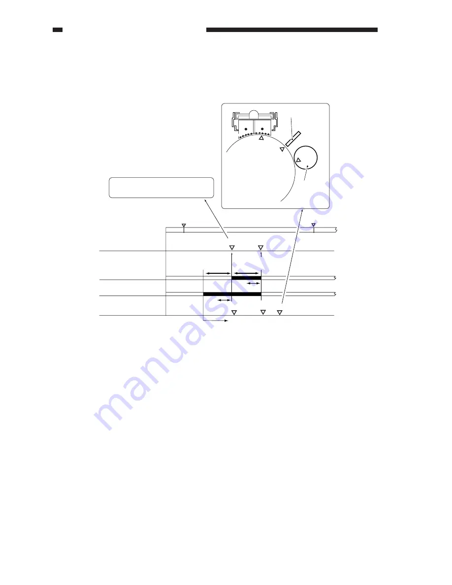
Figure 6-208 Sequence of Operations
WMUPR
WMUP
STBY
195˚C
200˚C
Potential sensor
Potential determined
Laser
Grid bias
Vg Vg
Pw
Pw
Potential control sequence started
VD
VL
Vdc
Vdc is computed based on this VD;
Vdc = VD - Vback (120 V)
Optimum grid
bias determined
Vg
VD
Vdc
Photosensitive drum
Potential sensor
Developing
cylinder
Optimum laser output
determined
F.
Determining the Optimum Developing Bias
An optimum developing bias (Vdc) is computed based on the optimum drum surface potential
(VD).
Summary of Contents for GP605
Page 3: ......
Page 4: ......
Page 24: ......
Page 56: ......
Page 78: ......
Page 116: ......
Page 124: ......
Page 148: ......
Page 150: ......
Page 168: ......
Page 170: ......
Page 250: ......
Page 252: ......
Page 342: ......
Page 390: ......
Page 392: ......
Page 464: ......
Page 466: ......
Page 512: ......
Page 514: ......
Page 572: ......
Page 574: ......
Page 590: ......
Page 592: ......
Page 854: ......
Page 870: ......
Page 874: ......