COPYRIGHT © 1999 CANON INC.
CANON GP605/605V REV.0 JAN. 1999 PRINTED IN JAPAN (IMPRIME AU JAPON)
vii
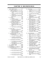
CHAPTER 5 LASER EXPOSURE SYSTEM
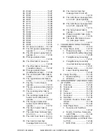
I.
OPERATIONS ............................ 5-1
A.
Outline .................................... 5-1
B.
Basic Sequence of Operations
(laser exposure system) ........ 5-4
II.
GENERATING THE BD SIGNAL 5-5
A.
Outline .................................... 5-5
B.
Flow of the BD Signal ............ 5-5
III. LASER DRIVER PCB ................. 5-7
A.
Outline .................................... 5-7
B.
Controlling the Laser Activation
............................................... 5-8
C. Controlling the Laser Intensity
............................................. 5-10
IV. Controlling the Laser Scanner Motor
.................................................. 5-12
A.
Outline .................................. 5-12
V.
DISASSEMBLY/ASSEMBLY .... 5-13
A.
Laser Unit ............................. 5-14
1.
Removing the Laser Unit
........................................ 5-14
2.
After Replacing the Laser Unit
........................................ 5-15
B.
BD Unit ................................. 5-16
1.
Removing the BD Unit .... 5-16
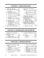
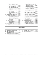
CHAPTER 6 IMAGE FORMATION SYSTEM
I .
PROCESSES .............................. 6-1
A.
Outline .................................... 6-1
B.
Basic Sequence of Operations
(image formation) ................... 6-3
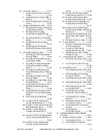
II . POTENTIAL CONTROL ............. 6-5
A.
Outline .................................... 6-5
B.
Determining the Optimum Grid
Bias ........................................ 6-8
C. Grid Bias Corrective Control .. 6-8
D. Determining the Optimum Laser
Output .................................... 6-9
E.
Laser Output Corrective control
............................................... 6-9
F.
Determining the Optimum
Developing Bias ................... 6-10
G. Potential Control for
Transparency Mode ............. 6-11
H. Target Potential Correction in
Each Mode ........................... 6-12
1.
Adjusting the Density during
Printing (PDL input) ........ 6-13
2.
Potential Control during High
Humidity Mode ................ 6-14
3.
Density Adjustment during
Printing (scanner input) .. 6-15
III . CONTROLLING THE CHARGING
MECHANISMS .......................... 6-16
A.
Controlling the Primary Charging
Mechanism........................... 6-16
1.
Outline ............................ 6-16
2.
Changing the Primary
Charging Level Setting ... 6-17
3.
Primary Charging Assembly
Cleaning Mechanism ...... 6-18
4.
Others ............................. 6-19
B.
Dust-Collecting Roller Bias .. 6-20
1.
Outline ............................ 6-20
C. Controlling the Pre-Transfer
Charging Mechanism ........... 6-21
1.
Outline ............................ 6-21
2.
Controlling the Output to Suit
the Environment (fuzzy
control) ............................ 6-22
3.
Pre-Transfer Charging
Assembly Cleaning
Mechanism ..................... 6-23
4.
Others ............................. 6-24
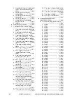
D. Controlling the Transfer Guide
Bias ...................................... 6-25
1.
Outline ............................ 6-25
2.
Controlling the Output to Suit
the Environment ............. 6-26
E.
Controlling the Transfer Charging
Mechanism........................... 6-27
1.
Outline ............................ 6-27
2.
Controlling the Output to Suit
the Environment (fuzzy
control) ............................ 6-28
3.
Correcting the Output at the
Trailing Edge of Paper .... 6-29
Summary of Contents for GP605
Page 3: ......
Page 4: ......
Page 24: ......
Page 56: ......
Page 78: ......
Page 116: ......
Page 124: ......
Page 148: ......
Page 150: ......
Page 168: ......
Page 170: ......
Page 250: ......
Page 252: ......
Page 342: ......
Page 390: ......
Page 392: ......
Page 464: ......
Page 466: ......
Page 512: ......
Page 514: ......
Page 572: ......
Page 574: ......
Page 590: ......
Page 592: ......
Page 854: ......
Page 870: ......
Page 874: ......


