background image

OSD Menu

68

Sub Menu

Setting Options (Bold: factory default)

Reference Level High

760 to 

1023

Sets the reference display level (high). [Reference Level High] is not 
displayed when [1023] is selected.

Reference Level Low

0

 to 256

Sets the reference display level (low). [Reference Level Low] is not 
displayed when [0] is selected.

Color

Sets the signals to be displayed and the color of signals exceeding the reference level.

Y

White
Red
Green
Blue
Yellow
Cyan
Magenta

[Y], [Cb], [Cr], [R], [G], [B]: Selects the color of the selected signal. 

Default value of each signal is shown below. 
Y (White), Cb (White), Cr (White), R (Red), G (Green), B (Blue)

[Reference Level High], [Reference Level Low]: Selects the color of the 

signal of the selected reference level. 
Default value of each reference level is shown below. 
Reference Level High (Magenta), Reference Level Low (Cyan)

Cb

Cr

R

G

B

Reference Level High

Reference Level Low

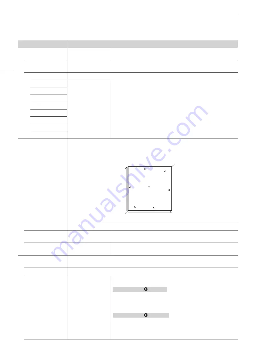
Vector Scope

7

Configures various settings for the vector scope. Vector scope displays the intensity of color signals 
and hue with the horizontal axis showing the color difference signal Cb and the vertical line showing 
Cr.

Red

Green

Yellow

Blue

Cyan

Magenta

(Cb, Cr) = (255, 255)

(Cb, Cr) = (0, 0)

Cr

Cb

Enable

On, 

Off

Switches the vector scope On, Off.

Target

75%

100%

Sets the target.

Position

5

Bottom Left

Bottom Right

Selects the display position.

Audio Level Meter

8

Configures various settings for the audio level meter. Displays the audio level of the selected channel 
number.

Enable

On, 

Off

Switches the audio level meter On, Off.

Channel Number  
(SDI)

2CH
4CH
6CH

8CH

Sets the number of channels displayed when SDI signal is input. Options 
change according to the setting for [SDI Group] under [Audio Settings].
When [SDI Group]   [CH1-CH8]
    [2CH]: CH1 to CH2
    [4CH]: CH1 to CH4
    [6CH]: CH1 to CH6
    [8CH]: CH1 to CH8
When [SDI Group]   [CH9-CH16]
    [2CH]: CH9 to CH10
    [4CH]: CH9 to CH12
    [6CH]: CH9 to CH14
    [8CH]: CH9 to CH16

Summary of Contents for DP-V2411

Page 1: ... read this guide including the safety and handling precautions Reading this guide will help you learn to use the video display properly Store this guide safely so that you can use it in the future English Instruction Manual Video Display ...

Page 2: ...ameters Anchor Point Setting 23 Enlarging the display Zoom function 23 Adjust image quality on left right side of screen image comparison mode 24 Performing calibrations 25 Export Import 26 Set Date Time 28 Inputting Characters 29 Using the Function F Buttons 29 Using the Channel CH Button 30 Checking Signal Information and Status of the Main Unit 32 Operating the video display using an external d...

Page 3: ...rence Indicates reference information CAUTION Indicates an item you must observe Adjustment Picture Mode Pressing the MENU button shows the OSD Menu levels You can move between the items and select from them Trademarks HDMI HDMI logo and High Definition Multimedia Interface are trademarks or registered trademarks of HDMI Licensing LLC in the U S and other countries VESA is a registered trademark o...

Page 4: ...Melville NY 11747 U S A Tel No 631 330 5000 For the customers in Canada CAN ICES 3 A NMB 3 A For the customers in Europe Warning This is a class A product In a domestic environment this product may cause radio interference in which case the user may be required to take adequate measures CANON INC 30 2 Shimomaruko 3 chome Ohta ku Tokyo 146 8501 Japan CANON EUROPA N V Bovenkerkerweg 59 1185 XB Amste...

Page 5: ...fire or electric shock Do not use the video display in the following places Doing so can cause fire electric shock or malfunction Close to a window when it is raining or snowing Places subject to high humidity and dust Places exposed to water and moisture such as bathrooms kitchens etc Places directly exposed to dust smoke or steam or nearby heaters and humidifiers Places where flammable gases may...

Page 6: ... Failing to do so can cause fire electric shock or malfunction For your safety unplug the power plug from the power outlet when not using the video display for extended periods of time Dust buildup on the power plug can cause fire Do not obstruct the access to the power plug so it can always be easily unplugged Failing to disconnect the power plug immediately after unusual circumstances have occur...

Page 7: ...ng 14 Taking such measures can be effective in reducing the risk of injury or damage but the effectiveness of the prevention measures cannot be guaranteed in all earthquakes Always follow the specified procedure to install the video display 12 If the installation is not performed correctly the video display may tilt or fall and cause injury Inspect the condition of the installation about once per ...

Page 8: ...the room is heated suddenly condensation may form on the surface or inside the equipment Note that the equipment may be damaged if it is used under such condition If condensation has formed on the surface or inside the equipment do not use the video display as it may get damaged Turn the power off and wait until the condensation has evaporated before using the video display Cleaning Before cleanin...

Page 9: ...d Handling Precautions 9 Disposing Do not dispose together with normal waste Do not include the video display in waste that will be taken to landfill Observe the rules and regulations of your local authorities when disposing ...

Page 10: ... CH3 30 4 CDL button For switching CDL mode 5 Function F button F1 to F8 29 6 MENU button 20 Jog dial 20 RESET button 20 7 Power button 18 8 Power indicator 18 9 USB port For connecting an external sensor for calibration 25 USB memory hub or color grading controller Element Tk made by Tangent Wave Ltd A q Headphone terminal 60 ...

Page 11: ...st not exceed 3 m 9 8 ft Otherwise communication error may occur and correct calibration may not be possible For safety do not connect any connector that may have excessive voltage to the terminal of the video display when connecting peripheral devices Pass through SD SDI signals are not output correctly Note About USB Memory Both FAT16 and FAT32 USB memory devices are supported Correct operation ...

Page 12: ...ing handle can be removed when storing the display on a rack or display shelf 1 Remove the two screws from the carrying handle as shown in the diagram below Use a hexagonal key 5 mm Do not lose the removed screws or the carrying handle Do not use these for other purposes CAUTION Ensure that you do not touch or damage the screen during this process When attaching a carrying handle to the video disp...

Page 13: ...oning material that is larger than the display 2 Remove the mounting screws x 2 from the left and right stands Do not lose the removed screws Do not use these screws for other purposes Attaching 1 Place the display with the screen facing down on a soft cloth or cushioning material that is larger than the display 2 Align the position of the stand and screw hole on the video display Alight the conve...

Page 14: ...stance from another person when performing this step Avoid touching the screen during this step as it may damage it For safety reasons when using the display for extended periods of time in a situation where it is subject to vibrations shocks or is tilted when moving in a live broadcast vehicle etc take additional measures to ensure the display remains fixed such as the use of the screw holes on t...

Page 15: ...splay is placed on a rack or display stand and ventilation around it is blocked by equipment placed above or below or in a surrounding area the operating temperature may increase causing a failure or overheating In order to maintain the operating temperature condition of the video display 0 C to 40 C make space of at least 1U 4 4 cm above and below and at least 4 cm 1 6 in space from its back Make...

Page 16: ... SDI Top left Mapping signal Input A Single input system Top right Mapping signal Input B Bottom left Mapping signal Input C Bottom right Mapping signal Input D Quad Link1 2 Sample Interleave 3G SDI Link 1 Input A Single input system Link 2 Input B Link 3 Input C Link 4 Input D Dual Link1 6G 3G SDI Link 1 Input A Two input systems Link 2 Input B Link 1 Input C Link 2 Input D Single Link 12G 6G 3G ...

Page 17: ...l is compatible with through output When signals are input from Input IN A connect the cable to the SDI OUT terminal of Input A HDMI input signal HDMI input terminal CAUTION Use a HDMI cable with the High Speed logo that complies with the HDMI standard When a non compliant HDMI standard cable is used the video display may not work normally for example video becomes choppy or nothing is displayed ...

Page 18: ...ply is connected and the video display s power is on Green flash during calibration or firmware update Amber lit during standby power supply is connected and the power to the video display is off Amber flash when error is detected CAUTION Check the specifications of the DC power supply input terminal and use a power supply that is compatible with the video display Using a power supply with incompa...

Page 19: ...n place with the holder 3 The holder should always be fastened in the position as shown in the illustration 4 Press the holder against the main unit 4 Make sure that there is no slack A Pulling the holder lock lever in the direction of the arrow will allow you to adjust the holder position 5 Detaching 1 Pull the holder lever in the direction of the arrow 6 and remove the AC power cord clamp from t...

Page 20: ... Resets the items to be adjusted using the slider and entered characters Jog dial or rotation Used to move to a different item and change settings Press Confirms settings or moves the selection frame up down 1 level The video display settings are changed from the OSD menu 1 Open the OSD menu Press the MENU button 2 Select the Main Menu Select the Main Menu item using the jog dial and press it to d...

Page 21: ...he settings that cannot be set are grayed out The following functions can be returned to their factory default settings or their anchor point 23 by pressing the RESET button after adjusting the image quality Contrast Brightness Chroma Sharpness Power Saturation Offset Slope When Picture Mode User 1 7 When executing calibration pressing the RESET button while adjusting the image quality will return...

Page 22: ... jog dial The indication changes to RGB R G and B Selecting RGB will allow you to adjust RGB as a whole 4 When adjustments are completed press the jog dial The screen returns to the original OSD menu Color temperature detailed settings xy values 1 Open the Color Temperature menu Adjustment Color Temperature 2 Select Custom xy You can set x and y individually using the jog dial 3 Select either x or...

Page 23: ...gs Reset All Settings resets saved anchor points and the settings return to their factory default values When calibration is executed the values are saved as anchor points Enlarging the display Zoom function 57 The zoom display position can be adjusted and the zoom magnification 2x 4x 8x can be selected 1 Open the Zoom menu Display Settings Zoom 2 Select Zoom Preset using the jog dial Select a pre...

Page 24: ...ed screen Note When in Image Comparison mode an icon showing which screen L R is selected for image quality Adjustment is displayed at the right top of the Adjustment menu screen The functions that cannot be used when the right screen is selected are as follows ACESproxy Ver 1 0 1 in Picture Mode Sub Menu items for Adjustment Contrast Backlight Control Boost Contrast HDR SDR View Calibration When ...

Page 25: ...e jog dial of the video display select OK and execute initialization 5 Place the universal measuring probe pointing at the center of the video display Set the mode dial of the universal measuring probe to MEAS and place the probe as shown below according to the displayed content Press the jog dial of the video display select OK and execute calibration Konica Minolta Universal Measuring Probe CA 31...

Page 26: ...LUT Import 44 1 Insert a USB memory stick into the USB port of the main unit 2 Open the LUT Import menu Adjustment Detail Settings LUT Import 3 Select the file using the jog dial In the Filename field search and display a file with extension clut in the root folder 4 Select the LUT type using the jog dial Select the LUT type by using User LUT Gamma LUT or Gamut LUT Refer to the Concept Drawing of ...

Page 27: ...from USB or User 1 to User 3 Export USB to the USB memory and User 1 to User 3 to the built in memory of the main unit 2Select Filename when USB is selected Factory default is dinfo_dpv2411 dat You can change the name of the file to be exported to the USB memory within 16 one byte characters including alphabetical characters numbers and symbols Importing 1Select Target from USB or User 1 to User 3...

Page 28: ...nized Set Date Time 75 This section describes how to set the video display Date Time The video display Date Time will be reset if the power cord is not connected for approximately 20 days 1 Open the Date Time menu System Settings Date Time A screen to input the Date Time appears 2 Set the Date Time using the jog dial The selection frame moves and numbers change as you operate the jog dial Repeat u...

Page 29: ...to confirm the settings Reference When selecting Cancel or pressing MENU button before selecting OK the settings will be reset and the previous screen will be displayed To erase a character in the selection frame press the RESET button of the video display Using the Function F Buttons You can assign functions to the F buttons on the video display to execute them instantly You can assign different ...

Page 30: ...in unit Open the Function Settings Various Function Function Button Guide menu and select On Pressing the jog dial while OSD is not showing will display the list of functions Using the Channel CH Button You can assign channels various settings related to input signal to the CH buttons on the video display and switch channels instantly 1 Open the Display Channel menu System Settings Function Channe...

Page 31: ...t set ITU R BT 709 Single Input Dual View Off Off Off Automatic Off Separator Off Off Off Off White CH CH6 CH7 CH8 CH9 CH10 to CH20 Input Configuration 12 3G HD SDI 12 3G HD SDI 12 3G HD SDI 12 3G HD SDI Not set Select Input Signal Automatic Automatic Automatic Automatic Automatic Image Division Automatic Automatic Automatic Automatic Automatic Format Automatic Automatic Automatic Automatic Automa...

Page 32: ...minal GPI You can operate the video display using an external device connected to the REMOTE terminal and execute the functions registered in each pin Remote operation is possible only when the video display is turned on Pin layout for REMOTE terminal Pin No Signal Factory default 1 Pin1 CH1 2 Pin2 CH2 3 Pin3 CH3 4 Pin4 Time Code 5 Pin5 Tally Green A tally appears at the top of the screen 6 Pin6 T...

Page 33: ...isplay right 1 Connect an external control device to the LAN terminal 2 Set SCREEN and INDEX to 0x0000 in the TSL Protocol settings 3 Open the In Monitor Display menu System Settings Network IMD Remote GPI Settings In Monitor Display 4 Select Control TSL Ver 5 00 using the jog dial This will allow operation from an external control device and display characters and tally lights 5 Select Position T...

Page 34: ... Settings CDL Export CDL Import CDL Preset Name Anchor CDL Reset CDL Detail Settings Boost Contrast LUT Import LUT Name LUT Delete YCbCr Color Matrix 2020 Constant Luminance 2020 Gamut Mapping Hybrid Log Gamma System HDR SDR View Calibration Copy Picture Mode Picture Mode Name Anchor Adjustment Reset Channel Settings 52 Select Channel Input Configuration Select Input Signal Image Division Format A...

Page 35: ...pect Marker Enable Mask Aspect Ratio Line Line Width Line Color Line Brightness H Position V Position Safety Zone Marker 1 2 Enable Aspect Ratio Area Size Rate Width dot Height dot Shape Line Width Line Color Line Brightness H Position V Position Area Marker Enable H Position V Position Width dot Height dot Mask Line Line Width Line Color Line Brightness Center Marker Enable Size Line Width Line C...

Page 36: ...ber SDI Channel Number HDMI Peak Hold Reference Level Test Pattern Screen Capture Capture Frame Hold Capture Source Playback File Finish Playback File Various Function Monochrome Blue Only Red Off Green Off Blue Off 2020 Out of 709 Gamut View Banner Function Button Guide OSD Position OSD Size Reduce Backlight Flash Camera Link Automatic Adjustment CINEMA EOS Color Gamut Gamma Color Temperature Col...

Page 37: ...or Display Remote GPI Display Name Power Indicator Button LED Settings Power Indicator Brightness Display Button LED Button Name Lighting Time sec Fan Settings Fan Control Fan Stop Compatible Settings HDMI Protect Settings Password Protect Target Protect Firmware Update Export Import Export Import Power on Setting Reset All Settings Signal Information 82 System Information 82 ...

Page 38: ...setting change automatically Automatic Adjustment CINEMA EOS 70 ACESproxy Ver 1 0 1 A mode to display ACESproxy videos in optimum gamma and color gamut Contrast2 0 to 6000 When Boost Contrast On 0 to 10000 Adjusts the white level of the image Increments of 1 When Boost Contrast is On Contrast BOOST is displayed Brightness 500 to 500 0 Adjusts the black level of the image Increments of 1 Chroma3 0 ...

Page 39: ... DCI Preset Gamut 1 to 709 Preset Gamut 1 to 2020 Preset Gamut 1 to DCI Preset Gamut 2 to 709 Preset Gamut 2 to 2020 Preset Gamut 2 to DCI Gamut LUT 1 to Gamut LUT 8 Sets the color range When Picture Mode User 1 7 or CINEMA EOS SYSTEM SMPTE C EBU ITU R BT 709 ITU R BT 2020 Adobe RGB DCI P3 Color gamut compliant to each standard Native Color gamut that can be displayed by this video display Cinema ...

Page 40: ...TU R BT 1886 Canon Log Canon Log 2 Canon Log 3 Select the preset gamma Canon Log HDR Canon Log 2 HDR Canon Log 3 HDR SMPTE ST 2084 PQ Hybrid Log Gamma Hybrid Log Gamma RGB Select the gamma for HDR display Preset Log 1 Preset Log 2 Selects the preset gamma Gamma LUT 1 to Gamma LUT 8 Selects an external LUT About Hybrid Log Gamma This video display supports the following two methods Hybrid Log Gamma...

Page 41: ...namic range from 0 to 1023 in 1 increments Setting procedures The explanation uses SMPTE ST 2084 PQ as an example When set at 1000 those areas that exceed 1 000 cd m2 are clipped and those that are 1 000 cd m2 or below are assigned to the dynamic range of the video display When displaying an image with a PQ of 1 000 cd m2 you can check the entire dynamic range of the image Also when displaying an ...

Page 42: ... instead of Gamma or Color Gamut Automatic Applied automatically Off Not applied Output Transform ITU R BT 709 ITU R BT 2020 DCI P3 When Picture Mode ACESproxy Ver 1 0 1 Displayed instead of Gamma or Color Gamut ITU R BT 709 ITU R BT 2020 DCI P3 ACESproxy is converted into respective mode Output Transform Surround Dim Surround Dark Surround When Picture Mode ACESproxy Ver 1 0 1 Displayed instead o...

Page 43: ...ment result and return to previously set image quality Detail Settings CDL Export Exports CDL parameters CDL Preset CDL 1 to CDL 15 All File Type CCC CDL Execute CDL Import Imports CDL parameters Filename CDL Preset CDL 1 to CDL 15 Execute CDL Preset Name You can specify the name of preset mode within 16 one byte characters including alphabetical characters numbers and symbols Anchor CDL You can t...

Page 44: ...betical characters numbers and symbols including file extensions Filename Select a filename LUT Type User LUT Gamma LUT Gamut LUT Select the LUT type Select LUT User LUT 1 8 Gamma LUT 1 8 Gamut LUT 1 8 Base Color Gamut SMPTE C EBU ITU R BT 709 Adobe RGB DCI P3 Native When LUT Type Gamut LUT Selects the color gamut used when creating the LUT Execute Performs import LUT Name You can specify the name...

Page 45: ...into RGB signals Non constant Luminance YUV signals are converted into RGB signals without changing gamma 0 45 2020 Gamut Mapping Gamut Mapping Clipping When Picture Mode or Color Gamut ITU R BT 2020 Gamut Mapping Mapping is performed on colors outside the native color gamut by Canon s unique method Clipping Colors outside the native color gamut are clipped by a general method Hybrid Log Gamma Sys...

Page 46: ...bration Copy Picture Mode14 When Picture Mode User 1 7 Copy the Picture Mode settings Picture Mode SMPTE C EBU ITU R BT 709 ITU R BT 2020 Adobe RGB DCI P3 User 1 2020 PQ User 2 2020 HLG User 3 DCI PQ User 4 to User 7 Select the Picture Mode User 1 7 Select from other than the currently set mode Execute Performs copy Picture Mode Name You can change the name of User 1 7 within 16 characters includi...

Page 47: ...ected the contrast may change temporarily in order to maintain gradation depending on the image If this is undesirable turn it Off and see if it improves You cannot set the right screen using Picture Mode if Picture Mode has been set differently for the left and right screens The right screen s setting will be the same as set for the left screen 5 Custom xy and Gain R G B or Bias R G B cannot be s...

Page 48: ...C Off 1 0 2 2 2 35 2 4 2 6 ITU R BT 1886 Canon Log Canon Log HDR SMPTE ST 2084 PQ Gamma LUT 1 to Gamma LUT 8 EBU Off 1 0 2 2 2 35 2 4 2 6 ITU R BT 1886 Canon Log Canon Log HDR SMPTE ST 2084 PQ Gamma LUT 1 to Gamma LUT 8 ITU R BT 709 ITU R BT 2020 Off 1 0 2 2 2 35 2 4 2 6 ITU R BT 1886 Canon Log Canon Log HDR Canon Log 2 Canon Log 2 HDR Canon Log 3 Canon Log 3 HDR SMPTE ST 2084 PQ Hybrid Log Gamma ...

Page 49: ...2020 PQ 1K is selected HDR Range SMPTE ST 2084 PQ settings become 1000 When ARRI LUT 2020 PQ 2K is selected HDR Range SMPTE ST 2084 PQ settings become 2000 10 It is not possible to set the function after selecting Picture Mode when the right screen is selected The right screen s setting will be the same as set for the left screen When Backlight Control settings are changed while Boost Contrast is ...

Page 50: ... ITU R BT 2020 Adobe RGB DCI P3 Color Range Automatic Automatic Automatic Automatic Automatic Automatic Input Transform Output Transform Output Transform Surround CDL Preset CDL 1 CDL 2 CDL 3 CDL 4 CDL 5 CDL 6 User LUT User LUT 1 User LUT 1 User LUT 1 User LUT 1 User LUT 1 User LUT 1 Boost Contrast Off Off Off Off Off Off YCbCr Color Matrix Automatic Automatic Automatic Automatic Automatic Automat...

Page 51: ...lor Range Automatic Automatic Automatic Automatic Automatic Automatic Input Transform Automatic Output Transform DCI P3 Output Transform Surround Dark Surround CDL Preset CDL 7 CDL 8 CDL 9 CDL 10 to 13 CDL 14 CDL 15 User LUT User LUT 1 User LUT 1 User LUT 1 User LUT 1 User LUT 1 User LUT 1 Boost Contrast Off Off Off Off Off Off YCbCr Color Matrix Automatic Automatic Automatic Automatic Automatic A...

Page 52: ...ct the input Factory default depend on the channel 31 Select Input Signal2 Automatic Quad Input Dual Input A B Dual Input C D Single Input A Single Input B Single Input C Single Input D Sets the signal display method 16 Automatic The display method is automatically determined to match the input signal Quad Input Four input signals Input A to Input D terminals are displayed Dual Input A B Two input...

Page 53: ... Dual Input C D Automatic Square Division 2 Sample Interleave Dual Link 3G SDI Multi View Dual 3 Automatic Automatically determined based on payload and displayed Square Division Displays a signal transmitted over four inputs as a single image 2 Sample Interleave Displays a signal transmitted divided into a 2K HD signal as a single image Dual Link 3G SDI Displays a Dual Link 3G SDI signal as a sin...

Page 54: ...iew Quad or Multi View Dual display sets the target terminal so that various markers except Grid Marker Time Code Wave Form Monitor Vector Scope and Camera Information are displayed Camera Information is available in the Multi View Quad display only Internal Sync On Off When Image Division Square Division Sets whether to synchronize four inputs On Force synchronization Off Do not force synchroniza...

Page 55: ...switching channels 2 Settings that can be set differ according to the input signal SD SDI Only Single Input A to Single Input D can be selected HDMI This is fixed to Automatic 3 For 2048 1080 images the images are displayed in reduced size when Screen Scaling is set to Automatic The left and right parts of the screen will be trimmed for display when anything other than Automatic is selected 4 HD S...

Page 56: ...ideo is scaled and displayed on the screen Native Input Resolution Displays the input signal without scaling 1920x1080 original 200 Doubles the vertical and horizontal dimensions 1920x1080 3840x2160 Automatic Enlarges to full screen 1920x1080 3840x2160 Anamorphic2 x2 0 x1 5 x1 33 Off Set when checking images photographed using an anamorphic lens Displayed in accordance with the set magnification ...

Page 57: ...ation to create copy new pixels This is useful as it enlarges the original pixels thus making any jagged lines visible Zoom3 Enlarges part of the video image The zoom function can be used when the resolution is 4096x2160 3840x2160 2048x1080 or 1920x1080 Zoom Preset Zoom 1 Zoom 2 Zoom 3 Off Sets the zoom display method There are three presets Magnification x2 x4 x8 Sets the display scale of zoom Po...

Page 58: ...rsion for 2 3 3 2 pulldown processed interlaced signal input Off Does not perform film cadence mode progressive conversion 1 In the following cases the maximum magnification is 200 even if Automatic is selected When Peaking or False Color is On In the following cases images are shown in reduced size when Automatic is selected 4096 2160 When Image Division Square Division is selected 2048 1080 When...

Page 59: ...ed while the video is paused the setting may not change correctly 5 Setting is disabled when Multi View Quad or Multi View Dual is selected 6 This can be set only when I P Conversion is set to Image Priority Cannot be set in the Multi View Quad or Multi View Dual display The setting is fixed to Off ...

Page 60: ... CH9 CH16 CH9 to CH16 CH9 Sets the audio to be output from the two channels L R of the headphone respectively The options differ according to the SDI Group setting CH R SDI SDI Group When CH1 CH8 CH1 to CH8 CH2 When CH9 CH16 CH9 to CH16 CH10 CH L HDMI CH1 to CH8 CH1 Sets the audio to be output from the two channels L R of the headphone respectively CH R HDMI CH1 to CH8 CH1 Volume 0 to 100 30 Sets ...

Page 61: ... color Mask is the blanking area outside the range of the marker Black Half 50 gray Off Turns mask off Aspect Ratio 16 9 15 9 14 9 13 9 4 3 2 39 1 2 35 1 1 896 1 1 85 1 1 66 1 Variable When Variable is selected 1 00 1 to 3 00 1 1 78 1 Sets the aspect ratio of the aspect marker The aspect ratio can be entered as a numeric value when you select Variable 0 01 1 increments The grayed out slider become...

Page 62: ... 9 4 3 2 39 1 2 35 1 1 896 1 1 85 1 1 66 1 Variable When Variable is selected 1 00 1 to 3 00 1 1 78 1 Sets the aspect ratio of the safety zone marker Variable The aspect ratio can be entered as a numeric value 0 01 1 increments The grayed out slider becomes active and can be used to set the aspect ratio Area Size 80 88 90 93 Variable Variable dot Sets the safety zone marker area size Variable The ...

Page 63: ...rker line H Position 65 to 65 0 Adjusts the marker horizontal position with the set aspect and size V Position 35 to 35 0 Adjusts the marker vertical position with the set aspect and size Area Marker1 Area Marker is used to check a specific area using a rectangular box Enable On Off Switches the area marker On Off H Position 0 to 4086 240 Sets the start position x coordinate to draw the rectangle ...

Page 64: ...gh Low Sets the brightness of the area marker line Center Marker3 Center Marker shows the center of the image Enable On Off Switches the center marker On Off Size Large Small Sets the size of the center marker Line Width Thick Normal Thin Sets the width of the center marker line Line Color White Red Green Blue Yellow Cyan Magenta Sets the color of the center marker line Line Brightness High Low Se...

Page 65: ...f the grid marker line 1 The marker is not displayed in the following cases When there is no signal unsupported signal or a channel with Input Configuration not set is selected When an enlarged image is displayed During the execution of Playback File under Screen Capture When a Test Pattern is displayed 2 When Area Size is set to Variable dot you cannot select Aspect Ratio 3 The marker is not disp...

Page 66: ...h When Peaking 2 Low Middle High Sets the central frequency of contour enhancement signals Range 3 3 0 Sets the width of the range to be colored Color White Red Green Blue Yellow Cyan Magenta Sets the color to be used False Color2 Displays different colors for the video s brightness levels to make it easier to check the exposure and brightness distribution Enable False Color 1 False Color 2 Off Sw...

Page 67: ...nd HDR Range information vertical line is displayed 255 4 0 50 100 0 Signal level IRE Horizontal resolution of video Enable On Off Switches the wave form monitor On Off Select Signal Y Cb Cr R G B Sets the waveform to be displayed Display Type All Line Sets the display type Line The data for one line is displayed Select Line 1 to 2160 Selects the line to be displayed when Line is selected Position...

Page 68: ...n Cb Cr R G B Reference Level High Reference Level Low Vector Scope7 Configures various settings for the vector scope Vector scope displays the intensity of color signals and hue with the horizontal axis showing the color difference signal Cb and the vertical line showing Cr Red Green Yellow Blue Cyan Magenta Cb Cr 255 255 Cb Cr 0 0 Cr Cb Enable On Off Switches the vector scope On Off Target 75 10...

Page 69: ...in the root folder of the USB memory Frame Hold On Off Pauses the video Capture Source All Video Selects the sources to capture All Everything is captured including video assistance functions such as markers and wave form monitor as well as OSD menu Video Only video signals are captured Playback File10 Select File Execute Plays back captured images Select File Selects a file Execute Plays back the...

Page 70: ... Off the screen may exhibit a flash in cases such as switching between scenes with a large difference in luminance You can use Reduce Backlight Flash to reduce this phenomenon Camera Link Sets the functions to link with Cinema EOS cameras and ARRI cinema cameras Automatic Adjustment CINEMA EOS When Picture Mode CINEMA EOS SYSTEM Input Configuration 12 3G HD SDI or 3G SDI RAW Sets whether or not to...

Page 71: ...n is always displayed Off Camera information is not displayed 1 Peaking cannot be displayed during the execution of Playback File under Screen Capture Enable changes to Off when the power is turned on again 2 False Color cannot be displayed during the execution of Playback File under Screen Capture Enable changes to Off when the power is turned on again When IRE in Type is selected HDR Range setti...

Page 72: ...H button F button assigned for Channel UP Channel DOWN or Select Channel under Channel Settings When changing Input Configuration or Select Input Signal under Channel Settings When Reset All Settings is executed 10 When playing back captured images on other DP V2411 or PC color may not be played back precisely 11 When CDL User LUT is set to User LUT Blue Only cannot be selected When power is resup...

Page 73: ... to 709 D65 DCI P3 to DCI P3 DCI P3 Cinema Gamut Cinema Gamut to 709 D65 Cinema Gamut to 2020 D65 Cinema Gamut to DCI P3 DCI P3 RAW Gamut Cinema Gamut to 709 D65 Cinema Gamut to 2020 D65 Cinema Gamut to DCI P3 DCI P3 Cinema EOS cameras DP V2411 Gamma Gamma HDR Range Canon Log Canon Log HDR Canon Log 2 Canon Log 2 HDR RAW Gamma Canon Log 3 Canon Log 3 HDR ST 2084 PQ SMPTE ST 2084 PQ 1000 Normal BT ...

Page 74: ...c Limited REC 2020 ARRI LUT 2020 ITU R BT 2020 2 2 Wide Gamut Log C ITU R BT 709 ARRI LUT 709 ITU R BT 709 2 2 ITU R BT 2020 ARRI LUT 2020 ITU R BT 2020 2 2 Automatic Limited ITU R BT 2020 PQ 1K ARRI LUT 2020 PQ 1K ITU R BT 2020 SMPTE ST 2084 PQ 1000 ITU R BT 2020 PQ 2K ARRI LUT 2020 PQ 2K ITU R BT 2020 SMPTE ST 2084 PQ 2000 Setting CDL User LUT Bypass to On when ARRI LUT is selected will change C...

Page 75: ...ures an IP address automatically with DHCP Auto IP Manual Configure an IP address and subnet mask manually Display 192 168 0 1 Subnet Mask 255 255 255 0 In Monitor Display The video display supports Television Systems Ltd s TSL UMD Protocol Ver 5 0 You can operate the video display using an external device connected to the LAN terminal and display characters and tally lights on the screen You can ...

Page 76: ...ected to the REMOTE terminal Operates while the GND No 8 Pin is connected to No s 1 to 7 shorting them Pin1 SMPTE C EBU ITU R BT 709 ITU R BT 2020 Adobe RGB DCI P3 User 1 2020 PQ User 2 2020 HLG User 3 DCI PQ User 4 to User 7 CINEMA EOS SYSTEM ACESproxy Ver 1 0 1 CH1 to CH5 Aspect Marker3 Safety Zone Marker 1 23 Area Marker3 Center Marker3 Grid Marker3 Time Code Wave Form Monitor Vector Scope Audi...

Page 77: ... connection compatibility with HDMI equipment HDMI Normal Compatible 1 Compatible 2 Normal All formats are supported Compatible 1 Set this option when video is not played correctly in Normal HDR signals of a luminance higher than that of the display main unit are not supported Compatible 2 Set this option when video is not played correctly in Normal or Compatible 1 4K50 00P 60 00P and HDR signals ...

Page 78: ... Target USB User 1 to User 3 Specify the save destination for the file to be imported Filename Displays files with the extension dat so you can select from among them Settings All Adjustment Channel Settings Display Settings Audio Settings Marker Settings Function Settings System Settings Select the settings to import Execute Performs import Power on Setting Last memory User 1 to User 3 You can se...

Page 79: ...ating approximately ten seconds later Since the temperature of the main unit has increased the fan rotates faster than usual Select Off to restart the fan The fan rotates faster than usual The fan may not stop in some conditions for example when used at a high temperature 6 The following settings cannot be exported or imported Adjustment Target values of Calibration including calibration results D...

Page 80: ... SDR View Zoom 3 Gain Frame Hold Bias Background Color xy Audio Settings SDI Group Picture Mode SMPTE C CH L EBU CH R ITU R BT 709 Volume ITU R BT 2020 Audio Switch Adobe RGB Marker Settings2 Marker Preset DCI P3 Marker 1 User 1 2020 PQ Marker 2 User 2 2020 HLG Marker 3 User 3 DCI PQ Marker 4 User 4 to User 7 Marker 5 CINEMA EOS SYSTEM Aspect Marker ACESproxy Ver 1 0 1 Safety Zoon Marker 1 CDL Use...

Page 81: ...20 Out of 709 Gamut View Camera Information System Settings Hide OSD3 Fan Stop 1 When changing channels with Channel UP DOWN the channels with Input Configuration 52 set to are skipped 2 When any marker settings are changed using an F button those changes will be applied to Enable under the currently selected Marker Preset 3 Hide OSD is a function to hide all OSD When On is selected OSD Separator ...

Page 82: ...DI 4 4 4 4 GBRA 10 bit 24 00 Progressive Progressive Transport Picture Single Link_1 Channel Input Configuration Format Resolution Picture Rate I P PsF Pixel Encoding Color Depth Matrix Range EOTF Max Luminance Peak Avg Display Luminance Max Min White Point Primary Color Red Primary Color Green Primary Color Blue CH4 HDMI Automatic 4096x2160 60 00P 4 2 2 YCbCr 10 bit ITU R BT 709 Full SMPTE ST 208...

Page 83: ...h aging Approximately 230 W At factory shipment Approximately 130 W Environmental Conditions Operating Temperature and humidity 0 40 C 32 104 F 20 85 RH no condensation Recommended range of temperature and humidity 15 30 C 59 86 F 20 to 80 RH no condensation Pressure 700 1060 hPa Storage Transporting Temperature and humidity 20 40 C 4 104 F 20 85 RH no condensation 41 60 C 105 140 F 20 30 RH no co...

Page 84: ... HD SDI 4 pass thru Head phone 1 stereo mini jack Supported impedance 32 Ω to 64 Ω Others USB 1 USB A receptacle terminal Universal Serial Bus Specification Revision 2 0 compliant LS Low Speed FS Full Speed HS High Speed mode compatible Compliant with Enhanced Host Controller Interface Specification for Universal Serial Bus Revision 1 0 LAN 1 RJ 45 terminal Compliant with IEEE802 3 10BASE TX IEEE8...

Page 85: ...7 387 15 2 408 16 1 438 17 2 417 16 4 100 3 9 100 3 9 147 5 8 188 6 7 4 239 9 4 44 1 7 62 2 4 40 1 6 36 1 4 160 6 3 396 15 6 15 0 6 15 0 6 4 M4 Depth 6 0 2 Max Center of panel 4 5 0 2 23 0 9 180 7 1 105 4 1 4 M4 Depth 7 0 3 Max Unit mm inch Front Rear Side Bottom ...

Page 86: ...Hz 1920x1080P 25 00 Hz 1920x1080PsF 25 00 Hz 1920x1080P 23 98 24 00 Hz 1920x1080PsF 23 98 24 00 Hz 2048x1080i 59 94 60 00 Hz 2048x1080i 50 00 Hz 2048x1080P 29 97 30 00 Hz SMPTE 292 1 SMPTE 428 9 SMPTE 428 19 SMPTE 2048 2 2048x1080PsF 29 97 30 00 Hz 2048x1080P 25 00 Hz 2048x1080PsF 25 00 Hz 2048x1080P 23 98 24 00 Hz 2048x1080PsF 23 98 24 00 Hz 3G SDI Level A 1280x720P 59 94 60 00 Hz 4 4 4 RGB 4 4 4...

Page 87: ...1 SMPTE 274M 4 2 2 YCbCr 12 bit 1920x1080P 25 00 Hz 4 4 4 RGB 4 4 4 YCbCr 12 bit 10 bit 4 2 2 YCbCr 12 bit 1920x1080PsF 25 00 Hz 4 4 4 RGB 10 bit 12 bit 4 4 4 YCbCr 12 bit 4 4 4 YCbCr 10 bit SMPTE 425 1 SMPTE 274M 4 2 2 YCbCr 12 bit 1920x1080P 23 98 24 00 Hz 4 4 4 RGB 4 4 4 YCbCr 12 bit 10 bit 4 2 2 YCbCr 12 bit 1920x1080PsF 23 98 24 00 Hz 4 4 4 RGB 10 bit 12 bit 4 4 4 YCbCr 12 bit 4 4 4 YCbCr 10 ...

Page 88: ...SMPTE 425 1 SMPTE 2048 2 4 2 2 YCbCr 12 bit 2048x1080P 25 00 Hz 4 4 4 RGB 12 bit 10 bit SMPTE 425 1 SMPTE 428 9 SMPTE 428 19 SMPTE 2048 2 4 4 4 X Y Z 12 bit 4 4 4 YCbCr 12 bit 10 bit SMPTE 425 1 SMPTE 2048 2 4 2 2 YCbCr 12 bit 2048x1080PsF 25 00 Hz 4 4 4 RGB 12 bit 10 bit SMPTE 425 1 SMPTE 428 9 SMPTE 428 19 SMPTE 2048 2 4 4 4 X Y Z 12 bit 4 4 4 YCbCr 12 bit 10 bit SMPTE 425 1 SMPTE 2048 2 4 2 2 Y...

Page 89: ...bit 10 bit 4 2 2 YCbCr 12 bit 1920x1080P 25 00 Hz 4 4 4 RGB 4 4 4 YCbCr 12 bit 10 bit 4 2 2 YCbCr 12 bit 1920x1080PsF 25 00 Hz 4 4 4 RGB 4 4 4 YCbCr 12 bit 10 bit 4 2 2 YCbCr 12 bit 1920x1080P 23 98 24 00 Hz 4 4 4 RGB 4 4 4 YCbCr 12 bit 10 bit 4 2 2 YCbCr 12 bit 1920x1080PsF 23 98 24 00 Hz 4 4 4 RGB 4 4 4 YCbCr 12 bit 10 bit 4 2 2 YCbCr 12 bit 2048x1080P 59 94 60 00 Hz 4 2 2 YCbCr 10 bit SMPTE 425...

Page 90: ...Y Z 12 bit 4 4 4 YCbCr 12 bit 10 bit SMPTE 425 1 SMPTE 372 SMPTE 2048 2 4 2 2 YCbCr 12 bit 2048x1080P 25 00 Hz 4 4 4 RGB 12 bit 10 bit SMPTE 425 1 SMPTE 372 SMPTE 428 9 SMPTE 428 19 SMPTE 2048 2 4 4 4 X Y Z 12 bit 4 4 4 YCbCr 12 bit 10 bit SMPTE 425 1 SMPTE 372 SMPTE 2048 2 4 2 2 YCbCr 12 bit 2048x1080PsF 25 00 Hz 4 4 4 RGB 12 bit 10 bit SMPTE 425 1 SMPTE 372 SMPTE 428 9 SMPTE 428 19 SMPTE 2048 2 ...

Page 91: ...E 428 9 SMPTE 428 19 SMPTE 2048 2 4 4 4 X Y Z 4 2 2 YCbCr 12 bit 2048x1080P 50 00 Hz 4 4 4 RGB 4 4 4 YCbCr 12 bit 10 bit 4 4 4 X Y Z 4 2 2 YCbCr 12 bit 2048x1080P 47 95 48 00 Hz 4 4 4 RGB 4 4 4 YCbCr 12 bit 10 bit 4 4 4 X Y Z 4 2 2 YCbCr 12 bit Dual Link 3G SDI Level B 1920x1080P 59 94 60 00 Hz 4 4 4 RGB 4 4 4 YCbCr 12 bit 10 bit SMPTE 425 3 SMPTE 372 SMPTE 274M 4 2 2 YCbCr 12 bit 1920x1080P 50 00...

Page 92: ...ave Level B 3840x2160P 29 97 30 00 Hz 4 2 2 YCbCr 10 bit SMPTE 425 3 SMPTE 372 SMPTE 274M 3840x2160P 25 00 Hz 3840x2160P 23 98 24 00 Hz 4096x2160P 29 97 30 00 Hz SMPTE 425 3 SMPTE 372 SMPTE 2048 2 4096x2160P 25 00 Hz 4096x2160P 23 98 24 00 Hz Quad Link HD SDI 3840x2160i 59 94 60 00 Hz 4 2 2 YCbCr 10 bit SMPTE 292 1 SMPTE 274M 3840x2160i 50 00 Hz 3840x2160P 29 97 30 00 Hz 3840x2160PsF 29 97 30 00 H...

Page 93: ...bit 12 bit 4 4 4 YCbCr 12 bit 4 4 4 YCbCr 10 bit SMPTE 425 1 SMPTE 274M 4 2 2 YCbCr 12 bit 3840x2160P 25 00 Hz 4 4 4 RGB 4 4 4 YCbCr 12 bit 10 bit 4 2 2 YCbCr 12 bit 3840x2160PsF 25 00 Hz 4 4 4 RGB 10 bit 12 bit 4 4 4 YCbCr 12 bit 4 4 4 YCbCr 10 bit SMPTE 425 1 SMPTE 274M 4 2 2 YCbCr 12 bit 3840x2160P 23 98 24 00 Hz 4 4 4 RGB 4 4 4 YCbCr 12 bit 10 bit 4 2 2 YCbCr 12 bit 3840x2160PsF 23 98 24 00 Hz...

Page 94: ...Y Z 12 bit 4 4 4 YCbCr 12 bit 10 bit SMPTE 425 1 SMPTE 2048 2 4 2 2 YCbCr 12 bit 4096x2160P 25 00 Hz 4 4 4 RGB 12 bit 10 bit SMPTE 425 1 SMPTE 428 9 SMPTE 428 19 SMPTE 2048 2 4 4 4 X Y Z 12 bit 4 4 4 YCbCr 12 bit 10 bit SMPTE 425 1 SMPTE 2048 2 4 2 2 YCbCr 12 bit 4096x2160PsF 25 00 Hz 4 4 4 RGB 12 bit 10 bit SMPTE 425 1 SMPTE 428 9 SMPTE 428 19 SMPTE 2048 2 4 4 4 X Y Z 12 bit 4 4 4 YCbCr 12 bit 10...

Page 95: ...096x2160P 59 94 60 00 Hz 4 2 2 YCbCr 10 bit SMPTE 425 5 SMPTE 428 9 SMPTE 428 19 SMPTE 2048 2 4096x2160P 50 00 Hz 4 2 2 YCbCr 10 bit 4096x2160P 47 95 48 00 Hz 4 2 2 YCbCr 10 bit 4096x2160P 29 97 30 00 Hz 4 4 4 RGB 4 4 4 YCbCr 12 bit 10 bit 4 4 4 X Y Z 4 2 2 YCbCr 12 bit 4096x2160P 25 00 Hz 4 4 4 RGB 4 4 4 YCbCr 12 bit 10 bit 4 4 4 X Y Z 4 2 2 YCbCr 12 bit 4096x2160P 23 98 24 00 Hz 4 4 4 RGB 4 4 4 ...

Page 96: ... 25 00 Hz 4 4 4 RGB 4 4 4 YCbCr 12 bit 10 bit 4 2 2 YCbCr 12 bit 3840x2160P 23 98 24 00 Hz 4 4 4 RGB 4 4 4 YCbCr 12 bit 10 bit 4 2 2 YCbCr 12 bit 3840x2160PsF 23 98 24 00 Hz 4 4 4 RGB 4 4 4 YCbCr 12 bit 10 bit 4 2 2 YCbCr 12 bit 4096x2160P 59 94 60 00 Hz 4 2 2 YCbCr 10 bit SMPTE 425 1 SMPTE 372 SMPTE 428 9 SMPTE 428 19 SMPTE 2048 2 4096x2160i 59 94 60 00 Hz 4 4 4 RGB 4 4 4 YCbCr 12 bit 10 bit 4 4 ...

Page 97: ...t SMPTE 425 1 SMPTE 372 SMPTE 2048 2 4 2 2 YCbCr 12 bit 4096x2160P 25 00 Hz 4 4 4 RGB 12 bit 10 bit SMPTE 425 1 SMPTE 372 SMPTE 428 9 SMPTE 428 19 SMPTE 2048 2 4 4 4 X Y Z 12 bit 4 4 4 YCbCr 12 bit 10 bit SMPTE 425 1 SMPTE 372 SMPTE 2048 2 4 2 2 YCbCr 12 bit 4096x2160PsF 25 00 Hz 4 4 4 RGB 12 bit 10 bit SMPTE 425 1 SMPTE 372 SMPTE 428 9 SMPTE 428 19 SMPTE 2048 2 4 4 4 X Y Z 12 bit 4 4 4 YCbCr 12 b...

Page 98: ...t 3840x2160P 23 98 24 00 Hz 4 4 4 RGB 4 4 4 YCbCr 12 bit 10 bit 4 2 2 YCbCr 12 bit 4096x2160P 59 94 60 00 Hz 4 2 2 YCbCr 10 bit SMPTE 425 5 SMPTE 372 SMPTE 428 9 SMPTE 428 19 SMPTE 2048 2 4096x2160P 50 00 Hz 4 2 2 YCbCr 10 bit 4096x2160P 47 95 48 00 Hz 4 2 2 YCbCr 10 bit 4096x2160P 29 97 30 00 Hz 4 4 4 RGB 4 4 4 YCbCr 12 bit 10 bit 4 4 4 X Y Z 4 2 2 YCbCr 12 bit 4096x2160P 25 00 Hz 4 4 4 RGB 4 4 4...

Page 99: ...2 bit 10 bit 4 2 2 YCbCr 12 bit 3840x2160P 23 98 24 00 Hz 4 4 4 RGB 4 4 4 YCbCr 12 bit 10 bit 4 2 2 YCbCr 12 bit 4096x2160P 25 00 Hz 4 4 4 RGB 4 4 4 YCbCr 12 bit 10 bit 4 4 4 X Y Z 4 2 2 YCbCr 12 bit 4096x2160P 23 98 24 00 Hz 4 4 4 RGB 4 4 4 YCbCr 12 bit 10 bit 4 4 4 X Y Z 4 2 2 YCbCr 12 bit 3840x2160P 59 94 60 00 Hz 4 2 2 YCbCr 10 bit 3840x2160P 50 00 Hz 4096x2160P 47 95 48 00 Hz 4096x2160P 59 94...

Page 100: ...80P 29 97 30 00 Hz 1920x1080P 25 00 Hz 1920x1080P 23 98 24 00 Hz 2048x1080P 59 94 60 00 Hz 2048x1080P 50 00 Hz 2048x1080P 29 97 30 00 Hz 2048x1080P 25 00 Hz 2048x1080P 23 98 24 00 Hz 3840x2160P 59 94 60 00 Hz 4 4 4 RGB 8 bit 4 4 4 YCbCr 8 bit 4 2 2 YCbCr 12 bit 4 2 0 YCbCr 12 bit 10 bit 8 bit 3840x2160P 50 00 Hz 3840x2160P 29 97 30 00 Hz 4 4 4 RGB 12 bit 10 bit 8 bit 4 4 4 YCbCr 12 bit 10 bit 8 bi...

Page 101: ...00 i 59 94 60 00 P 23 98 24 00 PsF 47 96 48 00 P 25 00 PsF 50 00 P 29 97 30 00 PsF 59 94 60 00 P 23 98 24 00 P 47 96 48 00 P 25 00 P 50 00 P 29 97 30 00 P 59 94 60 00 P 50 00 P 50 00 P 59 94 60 00 P 59 94 60 00 P 2048x1080 50 00 i 50 00 P 59 94 60 00 i 59 94 60 00 P 23 98 24 00 PsF 47 96 48 00 P 25 00 PsF 50 00 P 29 97 30 00 PsF 59 94 60 00 P 23 98 24 00 P 47 96 48 00 P 25 00 P 50 00 P 29 97 30 00...

Page 102: ... 48 00 P 25 00 P 50 00 P 29 97 30 00 P 59 94 60 00 P 50 00 P 50 00 P 59 94 60 00 P 59 94 60 00 P 4096x2160 50 00 i 50 00 P 59 94 60 00 i 59 94 60 00 P 23 98 24 00 PsF 47 96 48 00 P 25 00 PsF 50 00 P 29 97 30 00 PsF 59 94 60 00 P 23 98 24 00 P 47 96 48 00 P 25 00 P 50 00 P 29 97 30 00 P 59 94 60 00 P 47 95 48 00 P 47 95 48 00 P 50 00 P 50 00 P 59 94 60 00 P 59 94 60 00 P Displaying same frame ...

Page 103: ...00 P 59 94 60 00 P 1920x1080 25 00 P 50 00 P 1920x1080 23 98 24 00 P 47 96 48 00 P 2048x1080 59 94 60 00 P 59 94 60 00 P 2048x1080 50 00 P 50 00 P 2048x1080 29 97 30 00 P 59 94 60 00 P 2048x1080 25 00 P 50 00 P 2048x1080 23 98 24 00 P 47 96 48 00 P 3840x2160 59 94 60 00 P 59 94 60 00 P 3840x2160 50 00 P 50 00 P 3840x2160 29 97 30 00 P 59 94 60 00 P 3840x2160 25 00 P 50 00 P 3840x2160 23 98 24 00 P...

Page 104: ...ss may be in conflict or there may be a network communication error Check the network environment Invalid IP Address Enter the correct IP address Invalid Subnet Mask Enter the correct subnet mask Various settings CDL export The USB memory is full Use another USB memory or delete the content of the memory Failed to write file The USB memory may be defective or protected Check the USB memory LUT Var...

Page 105: ...connect it and then turn on the power If the message persists contact Canon Customer Center Fan error Panel error I F error System error Invalid operation due to high temperature The temperature inside the main unit is high Turn off the power and wait until the fan stops Input signal No Signal Displayed when there is no video signal input Unsupported Unsupported video signal is input Check the sup...

Page 106: ...has shut off as DC power voltage became insufficient for continued operation There may not be enough energy left if you are using the battery Connect a charged battery and turn the video display power on If you use another power source check the input voltage of the DC power supply Invalid Voltage Turn off power The power has shut off as the DC power input voltage exceeded the operational threshol...

Page 107: ... the output voltage may decrease suddenly and even turn off 0 V output when a threshold value is reached Before that a warning message about low input voltage may be displayed only briefly or not at all Connect a charged DC power supply or AC power supply The image does not display Set each item in Channel Settings according to input signal 52 The 3G SDI RAW signal image does not display At times ...

Page 108: ...e inside the main unit is high Configure settings after the internal temperature has lowered The fan may not stop in some conditions for example when used at a high temperature Use the video display at the operating temperature 83 or lower 71 77 Loud fan noise The fan operates at a faster speed than usual to lower the internal temperature if Fan Control is set to On and when the temperature inside...

Page 109: ...ts license agreement to be displayed This license agreement is as follows libupnp License Copyright c 2000 2003 Intel Corporation All rights reserved Redistribution and use in source and binary forms with or without modification are permitted provided that the following conditions are met Redistributions of source code must retain the above copyright notice this list of conditions and the followin...

Page 110: ...he software was developed by the University of California Berkeley The name of the University may not be used to endorse or promote products derived from this software without specific prior written permission THIS SOFTWARE IS PROVIDED AS IS AND WITHOUT ANY EXPRESS OR IMPLIED WARRANTIES INCLUDING WITHOUT LIMITATION THE IMPLIED WARRANTIES OF MERCHANTABILITY AND FITNESS FOR A PARTICULAR PURPOSE Copy...

Page 111: ...NG IN ANY WAY OUT OF THE USE OF THIS SOFTWARE EVEN IF ADVISED OF THE POSSIBILITY OF SUCH DAMAGE Newlib libm License Copyright C 1993 by Sun Microsystems Inc All rights reserved Developed at SunPro a Sun Microsystems Inc business Permission to use copy modify and distribute this software is freely granted provided that this notice is preserved ...

Page 112: ...Calibration 25 45 Camera Information 71 Camera Link 70 Canon Log CanonLog 2 Canon Log 3 40 CDL Export CDL Import 28 CDL User LUT Bypass 43 Center Marker 64 Channel Name 29 54 Channel Settings 52 Chroma 38 CINEMA EOS SYSTEM Picture Mode 38 Cinema Gamut to 709 39 Cinema Gamut to 2020 39 Cinema Gamut to DCI 39 Color Bars Test Pattern 69 Color Gamut 39 Color Range 42 Color Temperature 39 Compatible Se...

Page 113: ... ITU R BT 2020 38 L LAN 11 Language 75 Local Dimming 38 LTC 67 Luminance 45 LUT Import 26 44 M MAC Address 82 Marker Preset 61 Marker Settings 61 Marker TC WFM VEC Input 54 Monochrome 69 Multi View Dual 53 Multi View Quad 53 N Native Input Resolution Screen Scaling 56 Nearest Neighbor 57 Network 75 Network IMD Remote GPI Settings 75 O Offset 43 OSD Menu 20 34 OSD Position 70 OSD Size 70 Output Tra...

Page 114: ...2 Settings 27 78 Shape Trace 57 Sharpness 38 Signal Information 82 Single Input 52 Single Input Dual View 55 Slope 43 SMPTE C 38 Speed Priority 58 Square Division 53 Subnet Mask 75 System Information 82 System Settings 75 T Test Pattern 69 Time Code 67 U Usage Time 82 USB 10 25 26 User 1 7 38 User LUT 43 V Various Function Function Settings 69 Vector Scope 68 VITC 67 W Wave Form Monitor 67 White T...

Page 115: ...SA will have no responsibility Canon USA shall have no responsibility under this limited warranty for use of the Equipment in conjunction with incompatible peripheral equipment and or incompatible software Non Canon brand peripheral equipment and software which may be distributed with or be factory loaded on the Equipment are sold AS IS without warranty of any kind by Canon USA including any impli...

Page 116: ...TS EXPENSE FOR SUBSTITUTE EQUIPMENT OR SERVICE STORAGE CHARGES LOSS OR CORRUPTION OF DATA INCLUDING WITHOUT LIMITATION LOSS OR CORRUPTION OF DATA STORED ON THE EQUIPMENT S HARD DRIVE OR ANY OTHER SPECIAL INCIDENTAL OR CONSEQUENTIAL DAMAGES CAUSED BY THE USE MISUSE OR INABILITY TO USE THE EQUIPMENT REGARDLESS OF THE LEGAL THEORY ON WHICH THE CLAIM IS BASED AND EVEN IF CANON USA HAS BEEN ADVISED OF ...

Page 117: ...oftware as to which items Canon Canada will have no responsibility Canon Canada shall have no responsibility under this limited warranty for use of the Equipment in conjunction with incompatible computer equipment peripheral equipment and or incompatible software Non Canon brand peripheral equipment and software which may be distributed with or be factory loaded on the Equipment are sold AS IS wit...

Page 118: ...TORAGE CHARGES LOSS OR CORRUPTION OF DATA INCLUDING WITHOUT LIMITATION LOSS OR CORRUPTION OF DATA STORED ON THE EQUIPMENT S HARD DRIVE OR ANY OTHER SPECIAL INCIDENTAL OR CONSEQUENTIAL DAMAGES CAUSED BY THE USE MISUSE OR INABILITY TO USE THE EQUIPMENT REGARDLESS OF THE LEGAL THEORY ON WHICH THE CLAIM IS BASED AND EVEN IF CANON CANADA HAS BEEN ADVISED OF THE POSSIBILITY OF SUCH DAMAGES NOR SHALL REC...

Page 119: ...kerweg 59 1185 XB Amstelveen The Netherlands MÉXICO CANON MEXICANA S DE RL DE CV http www canon com mx 52 55 5249 4905 NEW ZEALAND www canon co nz Canon New Zealand Ltd 0800 222 666 within New Zealand only 64 09 489 0300 UNITED KINGDOM www canon co uk Canon UK Ltd CCI Service Centre Unit 130 Centennial Park Borehamwood Hertfordshire WD6 3SE 0844 369 0100 USA CANON U S A INC http pro usa canon com ...

Reviews: