


COPYRIGHT © 1998 CANON INC. CANON DADF-A1 REV.0 DEC. 1998 PRINTED IN JAPAN (IMPRIME AU JAPON)
2-3
CHAPTER 2 BASIC OPERATION
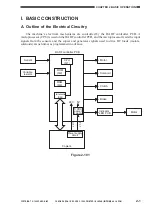
C. Inputs to the DADF Controller PCB
1. Inputs to the DADF Controller PCB (1/2)
DADF switch
MS1
MS2
S1
J203
J205
LED3
S3
S4
S5
S6
S7
J212
COM
J2-3
+24V
+5V
+5V
+5V
+5V
+5V
+5V
RFC
EMPS
ENTS
CVRSW
DCTS
EJTS1
SPRS
UPCC1
-4
1-2
J5-7
J9-B10
-B9
-B12
J9-B6
J5-3
J9-A1
J9-A4
-A6
-A5
-A3
-A2
-1
-2
-B8
-B7
-B11
-8
-9
3
1
2
1
3
1
2
3
J207
J208
1
2
3
1
2
3
1
2
3
1
2
1
3
2
1
3
2
3
1
2
2
4
1
2
J3-
NO
COM
NO
Upper cover switch
Original tray
paper sensor
Registration
paper sensor
Upper cover
sensor
Pick-up roller sensor
Delivery sensor 1
Pick-up sensor
DADF controller PCB
When the RDF is open, '0'.
When the upper cover is open, '0'.
When an original blocks the sensor, '1'.
When an original blocks the sensor, '1'.
When the upper cover is open, '0'.
(The light-blocking plate is at the sensor.)
When the pick-u roller is
at the home position, '1'.
(The light-blocking plate is at the sensor.)
When an original is detected, '1'.
(The light-blocking plate is at the sensor.)
When an original is detected, '1'.
(The light-blocking plate is at the sensor.)
Figure 2-103


