


COPYRIGHT © 1998 CANON INC. CANON DADF-A1 REV.0 DEC. 1998 PRINTED IN JAPAN (IMPRIME AU JAPON)
5-15
CHAPTER 5 TROUBLESHOOTING
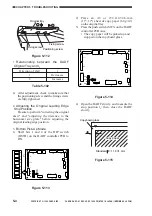
11) Shift bit 6 of the DIP switch DSW1 on the
DADF controller PCB back to OFF to end
service mode.
ON
12345678
LED1
LED2
SW1
TP1
J10
J15
J1
CB1
J2
J14
J12
J11
J7
J6
J13
J5
J9
J8
J3
6
1
B12
B1
2
1
1
3
1
2
1
3
1
2
13
1
14
2
A1
A12
1
1
1
1
9
10
1
4
2
2
8
1
7
1
DSW1
SW2
SW3
Figure 5-138
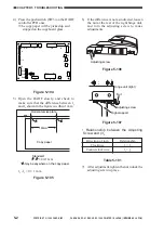
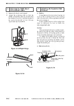
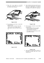
12) Mount the DADF controller cover.
d. Top Pick-Up Mode
1) Remove the screw, and detach the DADF
controller cover of the DADF.
DADF controller cover
Screw
Figure 5-139
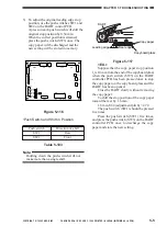
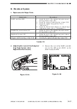
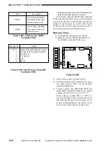
2) Shift bits 5 and 6 of the DIP switch DSW1
on the DADF controller PCB to ON to
select separation belt/feeding roller
cleaning mode (top pick-up).
ON
12345678
LED1
LED2
SW1
TP1
J10
J15
J1
CB1
J2
J14
J12
J11
J7
J6
J13
J5
J9
J8
J3
6
1
B12
B1
2
1
1
3
1
2
1
3
1
2
13
1
14
2
A1
A12
1
1
1
1
9
10
1
4
2
2
8
1
7
1
DSW1
SW2
SW3
Figure 5-140
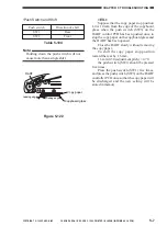
3) Press the push switch SW3 on the DADF
controller PCB. Put the test strip into the
middle separation assembly, and measure
the feeding power (Figure 5-141).
Points to Note When Taking
Measurements
1. Be sure that the three separation belts
are in contact with the test strip.
2. Be sure that the test strip is pulled
straight along the separation belt (Figure
5-131).
3. Be sure that measurements are taken
when the rear end of the test strip and the
rear end of the original tray are flush
(Figure 5-141).


