


COPYRIGHT © 1998 CANON INC. CANON DADF-A1 REV.0 DEC. 1998 PRINTED IN JAPAN (IMPRIME AU JAPON)
5-19
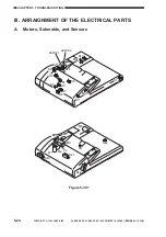
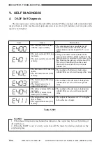
CHAPTER 5 TROUBLESHOOTING
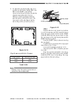
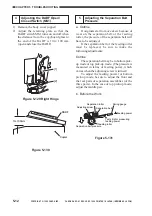
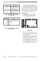
3) Place the copy paper in A4/LTR
orientation, and adjust the side guides to
the width of the copy paper.
Figure 5-148
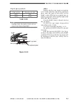
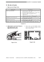
4) Press the push switch SW3 on the DADF
controller PCB.
•When the DADF controller reads data,
LED1 will turn on and then turn off
immediately; thereafter, LED2 will turn
on.
SW1
TP1
J10
J15
J1
CB1
J2
J14
J12
J11
J7
J6
J13
J5
J9
J8
J3
B12
B1
2
1
1
3
1
2
1
3
1
2
13
1
14
2
A1
A12
1
1
1
1
9
10
1
4
2
2
8
1
7
1
DSW1
SW2
SW3
Figure 5-149
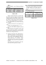
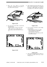
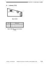
5) After LED2 has turned on, place the copy
paper on the document tray in a different
orientation (A4R/LTRR), and adjust the
side guides to the width of the copy paper.
Figure 5-150
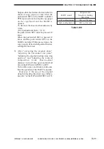
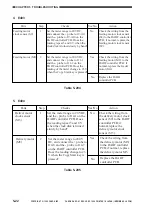
6) Press the push switch SW3 on the DADF
controller PCB.
• When adjustment ends successfully,
LED1 and LED2 on the DADF
controller PCB will turn on.
• When adjustment ends in failure, LED1
and LED2 will flash.
SW1
TP1
J10
J15
J1
CB1
J2
J14
J12
J11
J7
J6
J13
J5
J9
J8
J3
B12
6
1
B1
2
1
1
3
1
2
1
3
1
2
13
1
14
2
A1
A12
1
1
1
1
9
10
1
4
2
2
8
1
7
1
DSW1
SW2
SW3
LED1
LED2
Figure 5-151
7) Shift the bits of the DIP switch DSW1 on
the DADF controller PCB back to their
initial position.


