


COPYRIGHT © 1998 CANON INC. CANON DADF-A1 REV.0 DEC. 1998 PRINTED IN JAPAN (IMPRIME AU JAPON)
5-23
CHAPTER 5 TROUBLESHOOTING
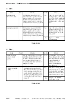
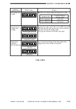
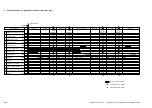
6. E411
Table 5-206
Parts
Step
Checks
Yes/No
Action
1
No
2
3
4
5
Yes
Yes
No
Original tray
paper sensor
(S1)
Registration
sensor
(S3)
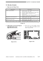
Connect the meter probes to the
following connectors on the
DADF controller PCB.
Is the reading 2.3 V or less
when there is nothing blocking
the sensor?
Original tray
paper sensor
(S1)
Registration
sensor (S3)
J5-8 J5-9
J9-
B12
J9-
B11
(+)
(-)
S1
LED3
J5-7 J5-9
J9-
B10
J9-
B9
(+)
(-)
Go to step 2.
Replace the DADF
controller PCB.
Is the light-receiving unit of
each sensor soiled with paper
lint or the like?
(S1)(S3)
Clean the light-receiving
unit of the sensor, and go
to step 3.
Original tray
paper sensor (S1)
LED3
Connect the meter probes to
the following connectors on the
DADF controller PCB. Is the
reading about 0.6 to 1.1 V?
Check the wiring from
LED3 to the DADF
controller PCB;
if normal, replace the
sensor or and LED3.
Sensors
After steps 2 and 3, check the
output according to the table in
step 1. At this time, is the
reading 1.2 V or less?
Yes
No
No
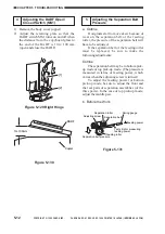
Adjust the position of
the sensor.
Sensor
Is the problem corrected after
step 4?
End.
Replace the sensor.


