


COPYRIGHT © 1998 CANON INC. CANON DADF-A1 REV.0 DEC. 1998 PRINTED IN JAPAN (IMPRIME AU JAPON)
5-5
CHAPTER 5 TROUBLESHOOTING
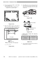
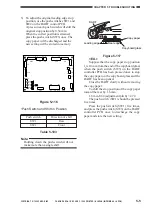
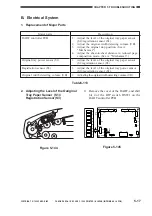
5) To adjust the original leading edge stop
position, use the push switches SW1 and
SW2 on the DADF control PCB.
A press on each push switch will shift the
original stop position by 0.34 mm.
When the correct position is attained,
press the push switch (SW3) once. The
copy paper will be discharged and the
new setting will be stored in memory.
TP1
J10
J15
J1
CB1
J2
J14
J12
J11
J7
J6
J13
J5
J9
J8
J3
B12
B1
2
1
1
3
1
2
1
3
1
2
13
1
14
2
A1
A12
1
1
1
1
9
10
1
4
2
2
8
1
7
1
DSW1
SW2
SW1
SW3
Figure 5-116
•Push Switch and Shift in Position
Table 5-103
Note:
Holding down the push switch will not
make more than a single shift.
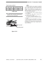
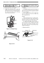
DADF
Leading edge
Rear edge
Copy paper
Copyboard glass
Figure 5-117
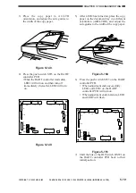
<EX.>
Suppose that the copy paper stop position
l
4
is 10 mm from the end of the copyboard glass
when the push switch (SW3) on the DADF
controller PCB has been pressed once to stop
the copy paper on the copyboard glass and the
DADF has been opened.
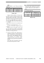
Close the DADF slowly without removing
the copy paper.
To shift the stop position of the copy paper
toward the rear by 1.6 mm,
1.6 mm
/
0.34 (adjustment pitch) = 4.70
The push switch (SW1) should be pressed
five times.
Press the push switch (SW1) five times,
and press the push switch (SW3) on the DADF
controller PCB once to discharge the copy
paper and store the new setting.
Direction of shift
Rear
Front
Push switch
SW1
SW2


