


CHAPTER 5 TROUBLESHOOTING
5-10
COPYRIGHT © 1998 CANON INC. CANON DADF-A1 REV.0 DEC. 1998 PRINTED IN JAPAN (IMPRIME AU JAPON)
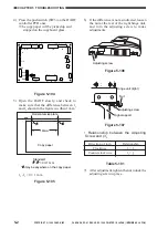
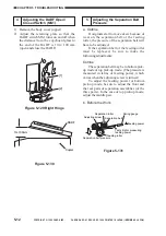
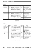
1) Shift bits 1, 2, and 4 of the DIP switch
(DSW1) on the DADF controller PCB to
ON.
2) Place two sheets of A4 or LTR copy paper
(64 g/m
2
) on the original tray.
Be sure that the copy paper matches the
DADF model: if A/B-configuration, use
A4 copy paper; if Inch-configuration, use
LTR cop paper.
ON
12345678
LED1
LED2
SW1
TP1
J10
J15
J1
CB1
J2
J14
J12
J11
J7
J6
J13
J5
J9
J8
J3
6
1
B12
B1
2
1
1
3
1
2
1
3
1
2
13
1
14
2
A1
A12
1
1
1
1
9
10
1
4
2
2
8
1
7
1
DSW1
SW2
SW3
Figure 5-126
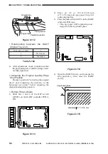
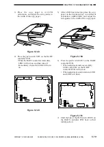
3) Press the push switch (SW3) on the DADF
controller PCB one.
• The copy paper will be picked up and
stopped on the copyboard glass.
4) Open the DADF slowly, and measure the
distance l
5
between the two sheets of copy
paper. Then, close the DADF.
Figure 5-127
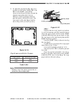
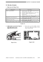
5) Use the push switches SW1 and SW2 on
the DADF controller PCB to adjust the
sheet-to-sheet distance.
5
5
Copyboard glass
Copy paper
[2]
Copy paper
[1]
Standard: = 0
±
3 mm
Figure 5-128
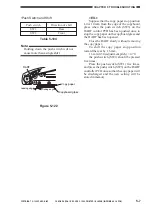
A single press on each push switch will
shift the copy paper [2]of Figure 5-128 by
0.34 mm. When the position is as desired,
press the push switch SW3 once to
discharge the copy paper and store the new
setting.
<EX.>
• Relationship between Push Switches
and Sheet-to-Sheet Distance
Sheet-to-sheet distance l
5
Increases
Decreases
Push switch
SW1
SW2
Table 5-107
SW1
TP1
J10
J15
J1
CB1
J2
J14
J12
J11
J7
J6
J13
J5
J9
J8
J3
B12
B1
2
1
1
3
1
2
1
3
1
2
13
1
14
2
A1
A12
1
1
1
1
9
10
1
4
2
2
8
1
7
1
DSW1
SW2
SW3


