background image

101

Setting Up Functions fr

om 
Menu

s

Checking the Information of the Projector

[Information]

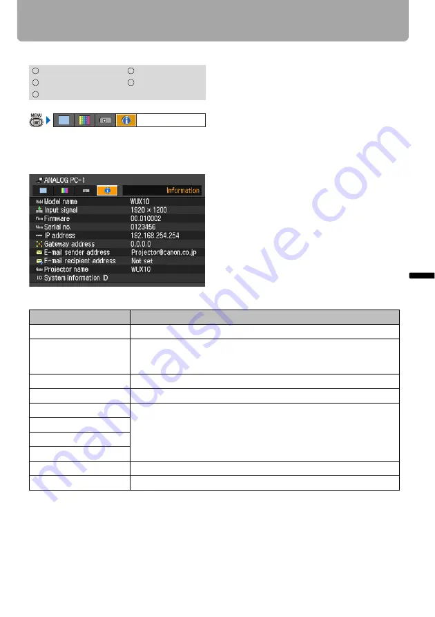
You can confirm the information about the 
signal types of the images projected and 
other projector-specific information.

Information shown

HDMI

COMPONENT

DIGITAL PC

VIDEO

ANALOG PC

Item

Meaning

Model name

Model name of this projector

Input signal

Details of the input signal currently selected
“Type of signal”, “resolution of signal”, “frequency” and 
other information is shown.

Firmware

Current firmware version

Serial no.

Serial number unique to this projector

IP address

Details of the network settings (

P106

)

[Not set] is shown for an item having no settings.

Gateway address

E-mail sender address

E-mail recipient address

Projector name

ID of this projector on the network

System information ID

This is an item of system information. Normally this is not displayed.

Information

Summary of Contents for 3288B002

Page 1: ...afety Instructions Before Use Projecting an Image Useful Functions Available During a Presentation Setting Up Functions from Menus Connecting the Projector to Network Appendix Index ENG MULTIMEDIA PROJECTOR User s Manual ...

Page 2: ...om Lens 1 5X zoom aspheric lens can project a 100 inch image when placed 3 m 9 8 to 4 4 m 14 4 away P31 Auto Setup Function for Making Setup a Breeze The focus and keystone distortion are automatically adjusted for quick and easy setup of projector P45 Equipped with HDMI Input Terminal Connecting the projector to AV equipment via HDMI terminal allows you to project high quality digital images P38 ...

Page 3: ...e remote control allows you to operate all functions of the projector In this document the buttons operation is shown as below Indicate the buttons to be pressed Adjusting the Image Size Use the ZOOM button to adjust the size of the proj Change the projector installation position if your de adjust it with the zoom function P31 1 Press the ZOOM button to pop up a window sho Remote control Top contr...

Page 4: ...8 Removing Noise P89 Blackened Out an Image Temporarily P64 Freezing the Picture P64 Adjusting the Volume P65 Muting the Sound P65 Zooming an Image P66 Showing the Elapsed Time P67 Resetting Password P97 Initializing a Network Setting P100 Resetting to the Default Setting P100 Reducing the Lamp Brightness P91 Using the Power Saving Mode P92 Turning on the Projector by Connecting the Power Cord P93...

Page 5: ...22 Bottom Side 23 Remote Control 24 Top Control 26 Input Terminals 27 Preparing the Remote Control 28 Installing Remote Control Batteries 28 Remote Control Operating Range 28 Projecting an Image 29 Steps for Setting Up the Projector and Projecting an Image 30 Setting Up the Projector 31 Placing in Front of the Screen 31 Placing on a Level Place 32 When Pointing the Projector Up 33 Connecting the P...

Page 6: ...cintosh OSX 49 AUTO PC 50 Performing the Auto PC Function 50 Adjusting the Image Size 51 Adjusting the Focus 52 Auto focusing 52 Manual focusing 52 Adjusting Keystone Distortion 53 Auto adjustment 53 Manual adjustment 53 Resetting the Keystone Adjustment 54 Selecting Screen Aspect and Aspect 55 Selecting Screen Aspect 55 Moving Image with 16 9 D Image Shift 57 Moving Image with 4 3 D Image Shift 5...

Page 7: ...Signal ANALOG PC Horizontal pixels 77 Adjust Input Signal ANALOG PC Vertical pixels 78 Selecting HDMI Input Level 78 Select HDMI Over Scan 79 Performing Progressive Processing 79 Selecting a Menu Position 80 Correcting the Screen Color 80 Reversing projection 81 Capturing a Logo 82 Selecting the User Logo Display Position 82 No Signal Screen 83 Screen When Blank 83 Selecting a Logo at Startup 84 S...

Page 8: ...Off the Network Function 99 Initializing network settings 100 Resetting to the Default Setting 100 Checking the Information of the Projector 101 Connecting the Projector to Network 103 Setting an IP Address 104 Setting IP Address of the Computer 104 Resetting the IP Address Setting of the Computer 105 Setting Network 106 Displaying the Network Configuration Screen 106 Setting the Network 107 Reset...

Page 9: ...acing the Lamp 124 Relationship between Aspect and Screen Aspect 125 When Projecting an Image from a Computer 125 When Projecting an Image from Image Software 127 Supported Computer Signal Types 128 Relationship between Screen Size and Projecting Distance 129 Glossary 130 Specifications 134 Projector 134 Remote Control 134 External View 135 ANALOG PC 2 COMPONENT IN terminal 135 Service Port CONTRO...

Page 10: ...wn in the Troubleshooting section at the end of this booklet If the problem still persists contact the service center or the dealer where you purchased the projector CAUTION TO REDUCE THE RISK OF ELECTRIC SHOCK DO NOT REMOVE COVER OR BACK THERE ARE NO USER SERVICEABLE PARTS INSIDE EXCEPT LAMPS REFER SERVICING TO QUALIFIED SERVICE PERSONNEL THIS SYMBOL INDICATES THAT DANGEROUS VOLTAGE CONSTITUTING ...

Page 11: ...d Allow for appropriate space above beside and behind of the projector cabinet for allowing air circulation and cooling of the projector Minimum clearances must be maintained If the projector is to be built into a compartment or similarly space the minimum distances must be maintained Do not cover the ventilation slot on the projector Heat build up can reduce the service life of your projector and...

Page 12: ... an unstable cart stand or table The projector may fall causing serious injury to a child or adult and serious damage to the projector Use only with a cart or stand recommended by the manufacturer or sold with the projector Wall or shelf mounting should be carried out in accordance with the manufacturer s directions and should use a mounting kit approved by the manufacturers An appliance and cart ...

Page 13: ... from the wall outlet and refer servicing to qualified service personnel under the following conditions a When the power cord or plug is damaged or frayed b If liquid has been spilled into the projector c If the projector has been exposed to rain or water d If the projector does not operate normally after following the operating instructions Adjust only those controls that are covered in the opera...

Page 14: ...he Battery Directive 2006 66 EC and or your national laws implementing those Directives If a chemical symbol is printed beneath the symbol shown above in accordance with the Battery Directive this indicates that a heavy metal Hg Mercury Cd Cadmium Pb Lead is present in this battery or accumulator at a concentration above an applicable threshold specified in the Battery Directive This product shoul...

Page 15: ...harmful interference to radio or television reception which can be determined by turning the equipment off and on the user is encouraged to try to correct the interference by one or more of the following measures Reorient or relocate the receiving antenna Increase the separation between the equipment and receiver Connect the equipment into an outlet on a circuit different from that to which the re...

Page 16: ...leakage of the battery fluid Remove the batteries when they have been exhausted or not in use for an extended period of time Be sure to replace both batteries at the same time Do not mix batteries of different types Insert batteries correctly according to the and markings If a fluid from a battery leaks and comes in contact with your skin rinse the affected skin thoroughly as soon as possible If a...

Page 17: ...adjustable foot The carrying bag is not designed to protect the projector from external shocks When carrying the projector with it put in the carrying bag do not give a shock to it drop it or place anything on it The projector may be dam aged or malfunctioned Do not transport the projector through a courier or transport service with the carrying bag Put the projector in an impact resistant transpo...

Page 18: ...aust outlet of air conditioning equipment Do not install the projector in a humid or dusty location or a position where there is a lot of oily or cigarette smoke Optical parts such as a lens and mirror may be stained resulting in poor picture quality If the projector is carried from a cold place to a warm place or the room tem perature is raised rapidly condensation may form on the lens and mirror...

Page 19: ...le of Contents Safety Instructions Before Use Projecting an Image Useful Functions Available During a Presentation Setting Up Functions from Menus Connecting the Projector to Network Appendix Index Before Use ...

Page 20: ...at the bottom of the pro jector When the projector is not in use attach the lens cap to protect the lens z Remote control z Batteries type AAA two for remote control z Computer connection cable DVI Mini D sub 15 pin 1 8 m 5 9 z Power cord 2 m 6 6 z Component cable RCA Mini D sub 15 pin 0 4 m 1 3 z Lens cap z Lens cap strap z Carrying bag z User s Manual CD ROM z Warranty card z Important Infomatio...

Page 21: ...tting the projector in the carrying bag Do not put the projector in the carrying bag until the cooling fan stops rotating The projector may be damaged due to the heat Attach the lens cap to the lens to protect it and put the projector in the carrying bag Replace the adjustable foot to prevent the damage on the projector When carrying the projector with it put in the carrying bag do not give a shoc...

Page 22: ...able foot lock button P33 Anti theft lock hole An anti theft wire cable available on the market can be connected Lens cap P20 Be sure to remove the lens cap during projection Failure to do so will result in fire hazards or cap deformation Caution Air intake vent Power cord connector P42 Top control P26 Cooling fan exhaust vents Infrared remote receiver P28 Do not block the air exhaust Failure to d...

Page 23: ...on Make sure to use the optional ceiling mount hanger You should never install the ceiling mount hanger by yourself If you mount the projector on the ceiling you have to invert the projected image by selecting Image flip H V from the menu P81 Lens cap strap insertion hole P20 Adjustable foot P33 Air intake vent Lamp cover P124 Rear adjustable foot for fine adjustment Air filter P122 Screw holes fo...

Page 24: ...en AUTO SET to adjust the focusing automatically D SHIFT KEYSTONE button P53 Corrects keystone distortion For keystone adjustment Press D SHIFT KEYSTONE and then AUTO SET to adjust the keystone automatically Moves the image up down left and right when 16 9 D image shift or 4 3 D image shift is selected P57 P58 Moves an image to the desired position D ZOOM button P66 Zooms the image in or out digit...

Page 25: ...U button P70 Displays a menu on the screen VOL button P65 Adjusts the sound volume Increases the volume Decreases the volume BLANK button P64 Toggles between display non dis play of image P TIMER button P67 Displays the time elapsed since this button was pressed AUTO PC button P50 Adjusts tracking and so on auto matically in accordance with signal from a computer when ANALOG PC 1 or ANALOG PC 2 is...

Page 26: ...from the menu INPUT button P48 Switches among input signals WARNING lamp P116 Flashes red when a problem has been detected on the projector POWER button lamp P42 P62 Turns the projector on or off Green The projector is on Flashing green The projector is being turned on Red The projector can be turned on Flashing red The projector is being turned off the lamp is being cooled Pointer VOL button P71 ...

Page 27: ...P35 P36 P39 P40 The audio input terminals correspond ing to 3 image input systems other than HDMI IN Each terminal receives the audio signal corresponding to DIGITAL PC ANALOG PC 1 ANA LOG PC 2 COMPONENT and VIDEO from the left The internal speaker outputs the audio signal for the selected image signal 5 AUDIO OUT Terminal P37 P41 The audio output terminal to output an audio to external AV equipme...

Page 28: ...ontrol within an angle of 30 in any direction from directly in front of the infrared remote receiver The remote control may be inoperative if there is an obstacle between the remote control and main unit or the infrared remote receiver on the main unit is exposed to direct sunlight or strong light of lighting equipment When you use two projectors at the same time you can change the channel setting...

Page 29: ... Contents Safety Instructions Before Use Projecting an Image Useful Functions Available During a Presentation Setting Up Functions from Menus Connecting the Projector to Network Appendix Index Projecting an Image ...

Page 30: ...ckering of the screen using the Auto PC P50 Adjusting the Image Size P51 Adjusting the Focus P52 Adjusting keystone Distortion P53 Making Fine Adjustments Selecting an Aspect Ratio of Projected Image Screen aspect and a Screen Mode Aspect P55 P59 Selecting an Image Mode P61 Do you want to project an image from a notebook computer Image projected properly Image projected properly No No For a notebo...

Page 31: ... distance between the projector and the screen projection distance as well as the zoom P51 For the relationship between the screen size and the projection distance see also the table listed in Relationship between Screen Size and Projecting Distance on page129 Screen size 40 60 80 100 150 180 200 250 300 Width cm 86 129 172 215 323 388 431 538 646 Height cm 54 81 108 135 202 242 269 337 404 Projec...

Page 32: ...ge using the rear adjustable foot Ceiling Mounting or Rear Projection You can mount the projector on the ceiling Ceiling mounted with it turned up side down or place it behind the screen Rear if you use a translucent screen For ceil ing mounting or rear projection you have to invert the projected image P81 Ceiling Mounting Rear Projection Make sure that the installation position is free from any o...

Page 33: ...rected with the auto keystone P45 or by using the keystone distortion adjust function P53 1 Lift the front side of the projector and push the adjusting foot lock button to extend the adjustable foot 2 Raise the image to the desired height angle then release the button to lock the foot in place If Keystone Distortion is Too Large If the keystone distortion is too large to adjust adjust the projecto...

Page 34: ...uipment P39 Amplified speaker P37 P41 Digital camera P39 Digital video camera P39 DVI I IN terminal can be used to connect only computer HDMI IN terminal can be used to connect only AV equipment DIGITAL PC ANALOG PC 1 HDMI HDMI IN terminal ANALOG PC 2 COMPONENT ANALOG PC 2 COMPONENT IN terminal Service terminal Reserved Video VIDEO IN terminal AUDIO IN terminal AUDIO OUT terminal LAN terminal Audi...

Page 35: ...47 Use full connected VGA cable in which all pins are connected otherwise an image will be projected improperly Use an audio cable without a built in resistor Using an audio cable with a built in resistor turns down the sound Computer Monitor output terminal mini D sub 15 pin Audio output terminal AUDIO OUT Supplied computer connection cable To input a corresponding audio signal Commercial audio c...

Page 36: ...udio cable with a built in resistor turns down the sound Monitor output terminal mini D sub 15 pin Audio output terminal AUDIO OUT To input a corresponding audio signal Commercial audio cable Commercial BNC cable To AUDIO IN To ANALOG PC 2 COMPONENT IN Computer Projector mini D sub 15 pin BNC Terminal Convert Cable commercial item mini D sub 15 pin BNC Terminal Convert Cable commercial item Monito...

Page 37: ...ossible to output sound of projected images to amplified speakers Use an audio cable without a built in resistor Using an audio cable with a built in resistor turns down the sound Commercial audio cable To AUDIO OUT Audio input terminal AUDIO IN RCA terminal Mini jack Projector Speaker ...

Page 38: ...ded here is just examples For more detailed information refer to the manual for the connecting AV equipment Connecting to Digital Video Output Terminal digital connection HDMI cable Input signal type HDMI P47 Digital video camera Digital video output terminal HDMI terminal Commercial HDMI cable HDMI cable connection simulta neously connects digital sound To HDMI IN AV equipment Projector ...

Page 39: ...pe VIDEO P47 Use an audio cable without a built in resistor Using an audio cable with a built in resistor turns down the sound RCA terminal RCA terminal Commercial audio cable Mini jack Commercial video cable To input a corresponding audio signal To VIDEO IN To AUDIO IN Audio output terminal AV equipment Projector Image output terminal ...

Page 40: ...the AV equipment to connect the supplied component cable Use an audio cable without a built in resistor Using an audio cable with a built in resistor turns down the sound RCA terminal Mini jack Audio output terminal To input a corresponding audio signal Commercial audio cable To AUDIO IN RCA Component terminal D terminal Image output terminal Commercial component cable with RCA RCA plugs Supplied ...

Page 41: ...to output sound of projected images to AV equipment or amplified speakers Use an audio cable without a built in resistor Using an audio cable with a built in resistor turns down the sound RCA terminal Mini jack Audio input terminal AUDIO IN To AUDIO OUT Commercial audio cable Projector Speaker ...

Page 42: ...ay suffer electromagnetic radiation problems or be subject to poor reception by TV and radio Wait at least 5 minutes before turning on the projector when you turn off the projector It may shorten the lamp life if you turn on the projector immediately after turning it off To save power unplug the power cord when not in use 3 Remove the lens cap and press the POWER button The POWER indicator flushes...

Page 43: ...nguage with the pointer buttons and press the OK button You can change the language from the menu at a later time P95 If the language selection screen is out of focus press the FOCUS and then AUTO SET buttons to make focus adjustment Changing Operations When Projector is Turned On You can change operations when the projector is turned on as follows You can turn on the projector by connecting the p...

Page 44: ...51 Use the FOCUS button to correct the focus adjustment if necessary P52 Use the D SHIFT KEYSTONE button to adjust keystone correction if necessary P53 Select the aspect ratio of the projecting image screen aspect or a screen mode aspect according to the aspect ratio of the screen type of input image signal and so on P55 P60 Select an image mode depending on the projecting image P61 Changing Noteb...

Page 45: ...ars press the INPUT button to select an appropriate input signal P48 If focusing keystone distortion and or screen color correction have not been performed properly manually adjust them Adjusting the focus P52 Correcting keystone distortion P53 and Correcting the screen color P80 If you select 16 9 D image shift or 4 3 D image shift for Screen aspect Auto setup will be disabled and the following s...

Page 46: ...he Screen Automatically 46 Performing the Auto Setup Press the AUTO SET button to perform the auto setup After the auto setup is complete the following window appears Press the OK button Remote control Top control ...

Page 47: ...rminals and connection cables Input signal Input terminal Types of connection cables HDMI HDMI IN HDMI cable commercial item DIGITAL PC ANALOG PC 1 DVI I IN DVI digital cable LV CA29 option ANALOG PC 1 ANALOG PC 1 DVI I IN Computer connection cable supplied item ANALOG PC 2 ANALOG PC 2 COMPONENT IN VGA cable commercial item BNC cable commercial item COMPONENT ANALOG PC 2 COMPONENT IN Component cab...

Page 48: ...gnal is received it is displayed in gray HDMI DIGITAL PC and ANALOG PC 1 may be displayed in gray even if they are ready for projection 2 The selection is toggled through available input signal types by pressing the INPUT button You can select the target input signal with Only the input signals displayed in white can be selected 3 Press the OK button to determine the input signal type If no button...

Page 49: ...t 1920 x 1200 or a resolution closest to the output signal resolution of the computer from the Resolution list 4 Close System Environment Setting window Windows Vista 1 Open the Control Panel from the start menu then select Appearance and Personalization Adjust screen reso lution in the Control Panel Home 2 Select 1920 x 1200 pixels or a reso lution closest to the output signal reso lution of the ...

Page 50: ...mply by select the input signal Performing the Auto PC Function Press the AUTO PC button to make projector adjustment Perform the following if the project image has not been properly adjusted with the auto PC function From Input signal select select an input signal type based on the resolution of the com puter P74 If the adjustment is still insufficient from Input signal settings select Total dots...

Page 51: ... if your desired image is too large or too small to adjust it with the zoom function P31 1 Press the ZOOM button to pop up a window shown at the lower right 2 Press the pointer buttons to adjust the image size 3 When the image size is determined press the OK button or the ZOOM button Remote control Top control Rough adjustment Fine adjustment Remote control Top control ...

Page 52: ...focusing Press the FOCUS button and then the AUTO SET button Manual focusing 1 Press the FOCUS button to pop up a window shown at the lower right 2 Press the pointer buttons to adjust the focus 3 When the focus is adjusted optimally press the OK button or the FOCUS button If you select 16 9 D image shift or 4 3 D image shift for Screen aspect the auto focus function will be disabled Remote control...

Page 53: ...r depending on type of input signal The result of keystone adjustment is memorized If you place the projector at the same position the keystone adjustment is not necessary Signals are processed digitally when keystone distortion is corrected The image may look different from the original one In addition the aspect ratio of the image may change If you select 16 9 D image shift or 4 3 D image shift ...

Page 54: ...ss the D SHIFT KEYSTONE button twice to display the Keystone reset window On the window select OK with and then press the OK button It cannot perform the keystone adjustment under the combinations shown in the following table Signal Signal type Resolution dots Screen Aspect Analog PC SXGA 1280 x 1024 4 3 UXGA 1600 x 1200 4 3 16 9 16 10 Compornent 1080i 16 9 16 10 HDMI 1080i 16 9 16 10 ...

Page 55: ...ou may need to change the setting depending on the resolution of the computer If the image is not projected with a desired aspect ratio see Relationship between Aspect and Screen Aspect in Appendix on page 125 Selecting Screen Aspect Select the aspect ratio of projecting image to the aspect ratio of the screen Perform the following steps to select the aspect ratio of the projecting image 1 Press t...

Page 56: ...t ratio of 16 9 You cannot correct the keystone distortion in this mode but you can move the image up or down with images being projected horizontally See the following page on how to shift the image 4 3 D image shift Select this when you use a screen with aspect ratio of 4 3 Suitable for projecting visual software having aspect ratio of 4 3 You cannot perform the keystone adjustment in this mode ...

Page 57: ... D SHIFT KEYSTONE button when 16 9 D image shift is selected for Screen aspect to pop up a window at the lower right 2 Use to move the image 3 When the image shift adjustment has been completed press the OK button Remote control Top control Remote control Top control Moves up the image Moves down the image ...

Page 58: ...e image 3 When the image shift adjustment has been completed press the OK button Resetting the Image Shift Perform the following steps to reset the image shift adjustment Press the D SHIFT KEYSTONE button twice to display the D image shift reset window On the window select OK with and then press the OK button Remote control Top control Remote control Top control Move the image to the left Move the...

Page 59: ...3 aspect ratio cannot be appropriately projected in the AUTO mode Zoom An image with 4 3 aspect ratio is projected in the center of the screen enlarged in 16 9 aspect ratio with the upper and lower portion of the image cut off Select this when pro jecting visual software having aspect ratio of 4 3 and black belts at the top and bottom of the image This mode is available when you select 16 10 16 9 ...

Page 60: ...e aspect ratio The selection is toggled among types for aspect ratios by pressing the ASPECT button For more details on the aspect ratios refer to When Projecting an Image from a Computer on page 125 You can also select any aspect ratio from the menu P73 Some aspect ratios may not appear depending on types of input signals Remote control ...

Page 61: ...age with quality suited for the presentation It is also suited to project visual software moving pictures with a high regard for the brightness Movie Select this to project common visual software moving pictures It is suited to easily enjoy the atmosphere of a moving theater in a dim room sRGB Select this if you want to project an image in the display mode conforming to the sRGB standard P130 It i...

Page 62: ...eration If you want to continue projecting press a button other than POWER or wait until the con firmation message disappears Wait at least 5 minutes before turning on the projector when you turn off the projector It may shorten the lamp life if you turn on the projector immediately after turning it off Using the projector for a long time may shorten the life of the lamp and internal optical compo...

Page 63: ...ty Instructions Before Use Projecting an Image Useful Functions Available During a Presentation Setting Up Functions from Menus Connecting the Projector to Network Appendix Index Useful Functions Available During a Presentation ...

Page 64: ...while blackening out the image The middle LED illumination lamp on the top control flush slowly while black ening out the image Freezing the Picture Useful when You want to perform a computer operation which is irrelevant to the proceedings of the presentation You want to stop a moving image Press the button to freeze the moving image The projector shows the following icon Press the button again t...

Page 65: ...he volume or mute setting on the computer if the volume level is too low You can also adjust the volume level of the speakers connected via the audio output terminal Muting the Sound Useful when You want to temporality mute the unnecessary sound You want to immediately mute the sound Press the button to mute the sound The projector shows the following icon Press the button again to cancel the MUTE...

Page 66: ... ing a presentation up to 12x Focusing on the current subject Press the button A part of the image is enlarged each time pressed The magnification appears on the screen You can move the area to the enlarged by using You can restore the original size of the image by pressing the button Remote control Remote control Projector ...

Page 67: ... of the presentation Press the button to start counting The elapsed time is displayed at the lower right corner of the screen Time is counted up to 59 59 Then the timer returns to 00 00 Press the button again to stop the timer Press the button while the timer is stopped The timer disappears from the screen Then press the button to start count ing from 00 00 Remote control ...

Page 68: ...68 ...

Page 69: ...tents Safety Instructions Before Use Projecting an Image Useful Functions Available During a Presentation Setting Up Functions from Menus Connecting the Projector to Network Appendix Index Setting Functions from Menus ...

Page 70: ...indicated as follows HDMI COMPONENT DIGITAL PC VIDEO ANALOG PC Input signal for which the menu item is displayed Input signal for which the menu items is not displayed System settings tab P92 You can set the operation of the projector Display settings tab P73 You can set the type of signal or the method of projection of the images input Image adjustment tab P85 You can adjust the image quality and...

Page 71: ... of Menu 1 Press the MENU button to display a menu window 2 Use to select a tab If the tab position is not highlighted in orange use to move the highlight to the top 3 Use to select a item Remote control Top control Remote control Top control Remote control Top control ...

Page 72: ... menu screen disappears 1 Press the OK button or and a list of the contents is displayed 2 Use to select contents 3 If you found the contents you desired press the OK button or Use to change the adjustment volume 1 Press the OK button to display a different screen 2 The follow the instruction on the screen 1 Press the OK button to display a different screen 2 Use to select contents and use to sele...

Page 73: ...n image is projected at an aspect ratio of 4 3 Select this if an image of 4 3 aspect ratio cannot be appropri ately projected in the AUTO mode Zoom An image with 4 3 aspect ratio is pro jected in the center of the screen enlarged in 16 9 aspect ratio with the upper and lower portion of the image cut off Select this when projecting visual software having aspect ratio of 4 3 and black belts at the t...

Page 74: ...orted by the projector see the table on page 128 Selecting an Input Signal Type VIDEO Input signal select You can select a proper signal type if a video image from your AV equipment is not projected correctly Press the OK button to accept your setting and then press the MENU button Auto is the factory default Refer to the User s Manual of your AV equipment connected to the projector to confirm the...

Page 75: ...ponent signal type Adjusting Input Signal ANALOG PC Total Dots Input signal settings Total dots You can adjust the total number of dots in the horizontal direction Adjust it when stripes are displayed on the screen Use to select a value When you have completed the adjust ment press the MENU button Perform this adjustment if the AUTO PC function P50 cannot adjust the project image correctly You can...

Page 76: ...put Signal ANALOG PC Hori zontal position Input signal settings Horizontal position You can adjust the horizontal position of the screen when the projected image is shifted in the horizontal direction Use to select a value As the value increases the screen moves to the left When you have completed the adjust ment press the MENU button Perform this adjustment if the AUTO PC function P50 cannot adju...

Page 77: ...ther for ANALOG PC 1 or ANALOG PC 2 Adjust Input Signal ANALOG PC Hori zontal pixels Input signal settings Horizontal pixels You can adjust the number of the pixels in the horizontal direction if the length of the screen is too long or too short in the hori zontal direction Use to select a value When you have completed the adjust ment press the MENU button Perform this adjustment if the AUTO PC fu...

Page 78: ...ls Press the OK button to accept your setting and then press the MENU button Auto is the factory default You can select this only when the type of signal sent from AV equipment is RGB The signal level is select automatically in Auto mode Some AV equipment may not support this If the HDMI output of your AV equipment allows switching between Normal and Expanded we recommend you to set Expanded The c...

Page 79: ...ails of the progressive pro cessing refer to the page 132 HDMI COMPONENT DIGITAL PC VIDEO ANALOG PC Off The entire input signals 100 are pro jected The images projected may be smaller than the full projection screen On Images are projected with disorders at their peripheral section of images trimmed off The central 95 of the images are projected A part of peripheral sections of images may be cut o...

Page 80: ... VIDEO ANALOG PC Menu position Display settings HDMI COMPONENT DIGITAL PC VIDEO ANALOG PC Normal Select this if a standard type of projec tion screen is used The images are projected in the light quality similar to that of natural light Green board Select this if a greenboard in dark green color is used for the projection screen The color quality similar to Nor mal is obtained on the greenboard Ad...

Page 81: ...HDMI COMPONENT DIGITAL PC VIDEO ANALOG PC None Select this if you project an image normally Ceiling mounted Select this if you project an image with the projector hung from the ceiling The projected images is inverted in both vertical and horizontal directions Rear Select this if you project an image from behind the screen The projected images is inverted in the horizontal direction Rear Ceil ing ...

Page 82: ...ogo Display Position User screen settings Logo position You can select a log display position Press the OK button to accept your setting and then press the MENU button Center is the factory default You cannot select Logo position if you have not captured a user logo on the Logo capture screen HDMI COMPONENT DIGITAL PC VIDEO ANALOG PC OK Press the OK button and the image in the red frame is capture...

Page 83: ...ly by pressing the BLANK button on the remote control Press the OK button to accept your setting and then press the MENU button Black is the factory default User logo is available only when a user s logo has been registered HDMI COMPONENT DIGITAL PC VIDEO ANALOG PC Black The screen is all black Displays no user logo Blue The screen is blue background Displays no user logo User logo Displays a user...

Page 84: ...e 56 Auto may be automatically selected for Screen aspect depending on the screen aspect setting HDMI COMPONENT DIGITAL PC VIDEO ANALOG PC Skip Projects an input signal immedi ately after turning on the projec tor Canon logo Displays the Canon logo cap tured at the factory User logo Displays a user logo captured on the Logo capture screen User screen settings Display settings Projector on HDMI COM...

Page 85: ...ode HDMI COMPONENT DIGITAL PC VIDEO ANALOG PC Image mode Image adjustment Standard Select this to project an image with near original quality and a high regard for reproduction of white It is suited to showing a computer screen or watching visual software moving pic tures in a bright room Presentation Select this to project an image with quality suited for the presen tation It is also suited to pr...

Page 86: ...e between the lightest and darkest portions of the image When you have completed the adjust ment press the MENU button The adjustment you have made is stored as an adjusted value of input sig nals being projected in an image mode HDMI COMPONENT DIGITAL PC VIDEO ANALOG PC Increases the brightness of an image Decreases the brightness of an image Brightness Image adjustment HDMI COMPONENT DIGITAL PC ...

Page 87: ...ct the obscure portion of an image due to too dark or bright When you have completed the adjust ment press the MENU button The adjustment you have made is stored as an adjusted value of input sig nals being projected in an image mode For the details of the gamma correction refer to the page 132 HDMI COMPONENT DIGITAL PC VIDEO ANALOG PC Increases the sharpness of an image Decreases the sharpness of...

Page 88: ...nt you have made is stored as an adjusted value of input sig nals being projected in an image mode HDMI COMPONENT DIGITAL PC VIDEO ANALOG PC R G B Gain Adjust the intensity of each color Increases the color intensity Decreases the color intensity R G B Offset Adjusts the color reproducibility of dark portions of each color Increases the color reproducibil ity of color Decreases the color reproduci...

Page 89: ...ustment Dynamic gamma Advanced adjustment Dynamic gamma You can adjust the gradation representa tion of light and dark portions of an image automatically Press the OK button to accept your setting and then press the MENU button The adjustment you have made is stored as an adjusted value of input sig nals being projected in an image mode HDMI COMPONENT DIGITAL PC VIDEO ANALOG PC Off Disables noise ...

Page 90: ...33 When you have completed the adjust ment press the MENU button Off is the factory default The adjustment you have made is stored as an adjusted value of input sig nals being projected in an image mode HDMI COMPONENT DIGITAL PC VIDEO ANALOG PC Off Disables the Auto fleshtone function L M H Specifies the intensity of the Auto flesh tone in three steps Advanced adjustment Image adjustment Auto fles...

Page 91: ... signals being projected in an image mode Resetting the Image Settings Reset You can reset the current image settings to the default settings Press the OK button to accept your setting and then press the MENU button Only the setting of the combined input signals being projected and an image mode is reset HDMI COMPONENT DIGITAL PC VIDEO ANALOG PC Normal Projects an image at the normal bright ness l...

Page 92: ...tton Off is the factory default The POWER indicator flashes red and green when the projector is in the Standby power management mode You cannot enable the Direct power on function see the next item if you select Off HDMI COMPONENT DIGITAL PC VIDEO ANALOG PC Auto focus Enables the auto focusing Auto keystone Enables the auto keystone cor rection Auto input Enables the auto input selec tion Auto scr...

Page 93: ...lt It does not beep if you mute the projec tor sound with the MUTE button on the remote control HDMI COMPONENT DIGITAL PC VIDEO ANALOG PC Off You need to press the POWER button to turn on the projector On You can turn on the projector only by connecting the power cable Before setting the direct power on to On be sure to set the Power man agement mode described on the preceding page to Standby or E...

Page 94: ...NT DIGITAL PC VIDEO ANALOG PC Off Disables the key lock Main unit Prohibit the operation from the main unit Use the remote control Remote control Prohibit the operation from the remote control Use the main unit The key lock function becomes effective from the moment the OK button is pressed after selecting Main unit or Remote control Be sure to press the OK button on the top control or remote cont...

Page 95: ... your setting and then press the MENU button On is the factory default The guide screen is shown when Power is turned off by pressing the POWER button P62 No input signal can be detected P44 An invalid button is pressed in the BLANK FREEZE or D ZOOM mode P64 66 HDMI COMPONENT DIGITAL PC VIDEO ANALOG PC English Germany French Italian Spanish Portuguese Swedish Russian Dutch Finnish Norwegian Turkis...

Page 96: ...ton to accept your setting and then press the MENU button Normal is the factory default You cannot extend the display time for the window indicating the completion of Auto setup P46 the guide window P95 the lamp replacement window preparation P123 or the lamp replacement window warning P123 You cannot use the button holding oper ation in the keystone adjustment HDMI COMPONENT DIGITAL PC VIDEO ANAL...

Page 97: ...rd for starting projection Press the OK button after selecting Reg ister password and the following screen for registering a password appears Enter a 4 digit password using e g The 4 digit password is entered from the left to right digits the password is auto matically registered Press the MENU button to abort the reg istration HDMI COMPONENT DIGITAL PC VIDEO ANALOG PC Off The projector can be use...

Page 98: ...NU button About the Display of the Lamp Counter The lamp counter displays the hours of use of the lamp in the following way Less than 1 800 hours Displayed in green bar 1 800 less than 2 000 hours Displayed in green and yellow bar For 1 800 1 900 hours a message Obtain a new lamp appears when power is turned on HDMI COMPONENT DIGITAL PC VIDEO ANALOG PC Do not reset the lamp counter except when you...

Page 99: ...n Other settings Network function You can save power if you turn off the net work function when you don t use the net work function Press the OK button to accept your setting and then press the MENU button Off is the factory default HDMI COMPONENT DIGITAL PC VIDEO ANALOG PC Off You can save energy by disabling the network function On You can enable the network function Other settings System settin...

Page 100: ...he menu item settings and restore the system settings to the factory defaults Press the OK button after selecting Fac tory defaults and the following screen for confirmation appears Press the OK button to accept your setting and then press the MENU button This function cannot reset the value of Lamp counter Language Remote control Input signal and Network set ting to default For factory defaults s...

Page 101: ...t signal Details of the input signal currently selected Type of signal resolution of signal frequency and other information is shown Firmware Current firmware version Serial no Serial number unique to this projector IP address Details of the network settings P106 Not set is shown for an item having no settings Gateway address E mail sender address E mail recipient address Projector name ID of this...

Page 102: ...102 ...

Page 103: ...ts Safety Instructions Before Use Projecting an Image Useful Functions Available During a Presentation Setting Up Functions from Menus Connecting the Projector to Network Appendix Index Connecting the Projector to Network ...

Page 104: ...ctly via a cross or straight type LAN cable 2 Turn on the power of the projector and computer 3 Select On for Network function in the projector menu P99 4 Open Control Panel from the Start menu then select Network and Internet Con nections Network Connections 5 Right click Local Area Connection and open Properties 6 Select Internet Protocol TCP IP and click the Properties button Take notes of the ...

Page 105: ...ettings click the OK button and then click the OK but ton on the Local Area Connection Properties window to close it Resetting the IP Address Setting of the Computer 1 Turn off the projector and remove the LAN cable 2 Follow the step 3 to 6 to restore the network setting to the original setting ...

Page 106: ...OK button The projector network configuration screen appears on the web browser The following information is displayed Projector name The name of the projector on the network MAC address The MAC address of the projector IP address The IP address of the projector Power Status The power status of the projector Lamp Time Normal Mode The total lamp used time in its normal mode Lamp Time Quiet Mode The...

Page 107: ...g items User name The user name for logging in the network New password The new password Confirm new password The password for confirmation 2 Click TCP IP enter appropriate values in the following field and click the OK button Setting items IP address The IP address of the projector Subnet mask The subnet mask of the projector Default gateway The default gateway of the projector ...

Page 108: ...s The IP address of the available SMTP mail server SMTP server port number The port number of the available SMTP mail server SNTP server IP address The IP address of the available SNTP mail server can be omitted Time zone The time zone of the installation site Mail resend interval The E mail resending interval at a transmission failure Setting range 0 59 seconds the factory default 10 seconds Mail...

Page 109: ...OGIN SMTP authentication CRAM MD5 SMTP authentication USER PASS POP before SMTP APOP POP before SMTP Setting items User name The user name for the mail authentication Password The password for the mail authentication Confirm password The password for confirmation POP3 server IP address The IP address of the POP3 server POP3 server port number The port number of the POP3 server The factory default ...

Page 110: ...tion that monitors the status of the projector SNMP consists of the manager a monitoring tool your PC and agent a monitored target the projector The information exchange group via SNMP is called a community The message which tells the status of the agent is called a SNMP trap This projector has the following SNMP traps coldStart it tells the SNMP agent is under initialization warmStart it tells th...

Page 111: ...work setting of the projector is now completed If you want to test the error report transmission click Send test mail filterMessage it tells that the air filter has reached its replacement tim ing UnknownError it tells that an unknown error was occurred Make sure to install the SNMP manager program on your PC before using the SNMP agent function Authentication and Encryption Protocols SNMP V3 for ...

Page 112: ...etwork Setting 1 Click Initialize in the menu screen 2 Click the OK button when the following dialog box is displayed If you want to restore to the factory setting from the projector perform Network set ting initialization from the menu ...

Page 113: ... to the lamp Error name Faulty lamp Text The lamp has burnt out Replace the lamp with a new one If the same warning occurs again the lamp drive circuit may be defective Contact your dealer Errors related to the lamp cover Error name Faulty lamp cover Text The lamp cover is open Check whether the lamp cover is installed properly If it is installed properly the lamp cover detection switch may be def...

Page 114: ... Aspect Select an aspect ratio P55 Image mode Select an image mode P61 Blank Blank out the image temporarily P64 Mute Mute the sound temporarily P65 Auto setup Perform the auto setup function P45 Auto PC Perform the auto PC function P50 For Input Aspect and Image mode select an item and click the Apply but ton Click the Refresh button to display the latest information Click the Back button to retu...

Page 115: ...ble of Contents Safety Instructions Before Use Projecting an Image Useful Functions Available During a Presentation Setting Up Functions from Menus Connecting the Projector to Network Appendix Index Appendix ...

Page 116: ... again the projector may be defective Contact your dealer Two flashes Faulty lamp The lamp has burnt out Replace the lamp with a new one If the same warning is experienced again the lamp drive circuit may be defective Contact your dealer Three flashes Faulty lamp cover The lamp cover is open Turn off the projector and unplug it from the power outlet then install the lamp cover and turn on the pro ...

Page 117: ... does not turn on when you connect the power cord You cannot release the safety device for safety reason Remove any obstacle that is blocking the air intake or exhaust vent and contact your dealer Cause Countermeasure Any connection cable is con nected incorrectly Check whether the projector is connected to the computer or AV equipment correctly P34 P47 20 seconds have not passed since the project...

Page 118: ... the computer Check whether the dual screen multi display mode is selected on the computer If the dual screen mode has been selected change it to the simultaneous display mode on the computer The output setting method varies among computer manufac turers For more detailed information refer to the User s Man ual that came with your computer The lens cap is not removed Remove the lens cap Cause Coun...

Page 119: ...ained Clean up the lens P121 The tracking is bad Adjust the tracking with the AUTO PC or Tracking func tion P50 P76 Cause Countermeasure The projected image is inverted in the vertical or horizontal direction The ceiling mounted rear projection setting is incorrect Check the Image flip H V setting in the Display settings menu P81 The dot clock of the inputted sig nal is 170MHz or higher with a BNC...

Page 120: ... the remote control operating range Check whether you are operating the remote control within the remote control operating range P28 There is an obstacle between the projector and the remote control Remove the obstacle between the infrared remote receiver of the projector and the remote control or point the remote control to an obstacle free path You are operating the remote con trol under an inap...

Page 121: ... the projector cools down sufficiently more than 1 hour before cleaning the projector Otherwise you may get burned or injured Before cleaning the projector be sure to disconnect the power plug from the AC outlet Other wise electric shock or fire may result Never use volatile cleaning liquid or benzine as these may damage the finish of the pro jector When using a chemical dust cloth make sure to re...

Page 122: ...rectly If the above screen is displayed when turning on the projector after cleaning the air fil ter select Yes Replacing the Air Filter Make sure to replace the air filter when replacing the lamp Follow the following procedure when replacing the air filter 1 Turn off the projector disconnect the power plug from the AC outlet and let the projector stand for at least 1 hour 2 Remove the filter cove...

Page 123: ... projector wait until the cooling fan stops disconnect the power plug from the AC outlet and let the projector stand for at least 1 hour Otherwise you may get burned because the main unit is very hot immediately after the projector is turned off Do not touch the inner glass surface when you replace the lamp Otherwise the projector s performance may degrade Make sure to handle the lamp carefully an...

Page 124: ...cover 3 Loosen two screws pull up the handle and then remove the lamp 4 Fully insert a new lamp and secure it with two screws After the installation be sure to push down the handle 5 Replace the lamp cover and tighten the screw 6 Turn on the projector 7 Bring up the menu and select System settings Other settings Lamp counter P98 8 Select Reset OK to reset the lamp counter Lamp cover Screw Screw La...

Page 125: ...puter Screen Object of Projection Aspect Setting 16 10 WUXGA 16 10 Project an image in a largest possible size on the screen Auto or Full WSXGA WSGA 16 10 Project an image in a largest possible size on the screen Auto or Full Project the computer screen in the original resolution True size WXGA Project an image in a largest possible size on the screen Auto Project the computer screen in the origin...

Page 126: ...screen in the original resolution True size WXGA Project an image in a largest possible size on the screen Auto Project the computer screen in the original resolution True size UXGA 4 3 Project an image in a largest possible size on the screen Auto or 4 3 SXGA XGA SVGA VGA 4 3 Project an image in a largest possible size on the screen Auto or 4 3 Project the computer screen in the original resoluti...

Page 127: ... not projected correctly select 16 9 as screen aspect If you project the 16 9 image with black borders at top and bottom such as in the terres trial movie broadcasting you can project the 16 9 image fully on the screen by select ing Zoom in Aspect Zoom is available when 16 10 16 9 or 16 9 D image shift is selected for the screen aspect and HDMI 480p COMPONENT 480p 480i or VIDEO is selected for the...

Page 128: ...469 59 901 WUXGA 1920 x 1200 74 04 59 95 SXGA 1152 x 864 64 196 70 39 1152 x 900 61 17 65 28 61 846 66 00 71 399 75 64 1280 x 960 60 00 60 00 1280 x 1024 62 50 58 63 63 337 59 98 63 364 59 95 63 735 60 01 63 791 60 18 63 899 60 00 63 981 60 02 71 694 67 19 76 97 72 00 79 976 75 03 81 135 76 11 SXGA 1400 x 1050 63 981 60 02 UXGA 1600 x 1200 75 00 60 00 MAC LC 13 640 x 480 34 967 66 60 MAC13 640 x 4...

Page 129: ...280 158 233 175 3 9 12 8 5 8 19 0 140 302 188 302 170 251 188 4 2 13 8 6 2 20 3 150 323 202 323 182 269 202 4 5 14 8 6 7 22 0 160 345 215 345 194 287 215 4 8 15 8 7 1 23 3 170 366 229 366 206 305 229 5 1 16 7 7 5 24 6 180 388 242 388 218 323 242 5 4 17 7 8 0 26 3 190 409 256 409 230 341 256 5 8 19 0 8 4 27 6 200 431 269 431 242 359 269 6 1 20 0 8 9 29 2 210 452 283 452 254 377 283 6 4 21 0 220 474...

Page 130: ...r minal on this projector with the supplied computer cable Select ANALOG PC 1 at the time of projection Or connect the analog RGB output termi nal on your computer and ANALOG PC 2 COMPONENT IN terminal on this projector with a commercial VGA cable Select ANALOG PC 2 at the time of projection An abbreviation for High Definition Multi media Interface which is a digital video signal connection interf...

Page 131: ...ing broken down into the brightness signal Y color signal C B Y color difference signal and R Y color dif ference signal Its image quality is higher than that of the composite video This sys tem can project a better quality image as compared with the composite signal sys tem Connect the component video termi nal on the AV equipment and the ANALOG PC 2 COMPONENT IN terminal on this projector with a...

Page 132: ...nes are noticeable on a fast moving picture A parameter that shifts the reproduction range of a brightness signal from black to white within an image signal toward the higher or lower level of brightness The reproducibility of the dark tone is mainly changed Since you can adjust the offset for each RGB color in this projector you can also adjust colors The offset is normally adjusted with the gain...

Page 133: ...ed user You can adjust color bal ance and color level for 6 axis of RGB red green blue and CMY cyan magenta yellow of the projected image to make a fine color adjustment You can perform the 6 axis color adjustment in the image adjustment menu 6 axis color adjust P90 ...

Page 134: ...1080i 720p 576p 480p VIDEO input NTSC PAL SECAM NTSC4 43 PAL M PAL N Input terminals DVI I IN terminal DIGITAL PC ANALOG PC 1 DVI I connector 29 pin HDMI IN terminal HDMI ver 1 3 10 bit deep color ANALOG PC 2 COMPONENT IN terminal ANALOG PC 2 COMPONENT mini D sub 15 pin VIDEO IN terminal Composite RCA CONTROL terminal RS 232C mini D sub 9 pin Audio Input terminal Audio signal stereo mini jack x 3 ...

Page 135: ...t and component input are the same Mini D sub 15 pin 41 4 mm 1 6 61 5 mm 2 4 284 mm 11 2 336 mm 13 2 114 mm 4 5 50 mm 2 0 48 mm 1 9 37 mm 1 5 75 mm 3 0 75 mm 3 0 61 5 mm 2 4 193 mm 7 6 73 mm 2 9 Screw Holes for installation of ceiling mount hanger M4 x 6 1 R 9 5 V power 2 G 10 Ground Vertical sync 3 B 11 Monitor ID0 4 Monitor ID2 12 DDC data 5 Ground Horizontal sync 13 Horizontal sync 6 Ground R 1...

Page 136: ...eric code 0Dh Get GET BRI CR 47h 45h 54h 20h 42h 52h 49h 0Dh Sharpness Setting SHARP value CR 53h 48h 41h 52h 50h 3Dh numeric code 0Dh Get GET SHARP CR 47h 45h 54h 20h 53h 48h 41h 52h 50h 0Dh Contrast Setting CONT value CR 43h 4Fh 4Eh 54h 3Dh numeric code 0Dh Get GET CONT CR 47h 45h 54h 20h 43h 4Fh 4Eh 54h 0Dh Aspect ratio Auto ASPECT AUTO CR 41h 53h 50h 45h 43h 54h 3Dh 41h 55h 54h 4Fh 0Dh Full AS...

Page 137: ...TO SET 46 Auto setup 45 92 B Beep 93 BLANK 64 Brightness 86 C Carrying bag 17 21 Ceiling mounted 32 81 Channel setting 94 Color adjustment 88 COMPONENT 40 47 Component 131 Composite 130 Connecting the projector to the computer 35 Contrast 86 D D ZOOM 66 D SHIFT KEYSTONE 53 57 DIGITAL PC 36 47 Digital PC 130 Direct power on 93 Display resolution preparing the computer 49 Display settings menu 70 Di...

Page 138: ...ment 43 Power management mode settings 92 Power saving power management 43 Progressive 79 132 Projecting distance 31 129 Projector on 84 P TIMER 67 R Rear projection 32 81 Register password 97 Remote control 24 28 94 Reset 91 100 Resolution 131 Reverse projection ceiling mounted rear projection 32 81 S Screen aspect 55 84 125 Screen color 80 Screen size 129 Screen when blank 83 Selecting a languag...

Page 139: ...139 Index Index V Vertical pixels 78 Vertical position 77 VIDEO 39 47 130 VIDEO IN terminal 27 39 VOL 65 W WARNING lamp 26 116 Z ZOOM 51 Zoom Aspect 59 Zoom image size 51 Zooming an Image 66 ...

Page 140: ...0 cm 16 in to 60 cm 24 in Part No RS CL08 Ceiling mount pipe 60 cm 24 in to 100 cm 40 in Part No RS CL09 DVI digital cable Part No LV CA29 This part is used to hang the projector from a ceiling For more detailed information refer to the instruction manual that comes with the ceiling mount hanger RS CL07 ...

Page 141: ...141 ...

Page 142: ...tical position P77 Horizontal pixels P77 Vertical pixels P78 HDMI input level HDMI P78 Auto Normal Expanded HDMI over scan HDMI P79 Off On Progressive VIDEO COMPONENT HDMI P79 Off On Auto Menu position P80 Screen color Normal P80 Greenboard Adjust Red Green Blue Image flip H V None P81 Ceiling mounted Rear Rear Ceiling mounted User screen settings Logo capture OK Cancel P82 Logo position Upper L P...

Page 143: ...s E mail sender address E mail recipient address Projector name System information ID Auto setup P92 Auto focus Off On Auto keystone Off On Auto input Off On Auto screen color Off On Return Power management mode Off P92 Standby Exit Direct power on Off P93 On Beep Off P93 On Key lock Off P94 Main unit Remote control Remote control Ch1 P94 Ch2 Language English Polish P95 Germany Hungarian French Cz...

Page 144: ...asse 11 A 1230 Wien Austria CANON España S A C Joaquín Costa 41 28002 Madrid Spain CANON PORTUGAL S A Rua Alfredo da Silva 14 Alfragide 2610 016 Amadora Portugal CANON Belgium N V S A Berkenlaan 3 1831 Diegem Mechelen Bel gium CANON Netherland NV Neptunusstraat 1 2132 JA Hoofddorp The Netherlands CANON LUXEMBOURG S A Rue des Joncs 21 L 1818 Howald Luxem bourg CANON DANMARK A S Knud Hoejgaards Vej ...

Reviews: