The EdgeAccess Universal Chassis System
2361 Modem Users Manual
7-4
Important: Remember that the rackmount modems must be placed in a special slot
configuration, as follows:
•
The primary modem must be placed in an odd slot
•
The secondary modem must be placed in the even slot to its immediate right.
Example: Slot 3 must be paired with slot 4, and slot 7 must be paired with slot 8. In
such a configuration, the modems in slot 3 and 7 would be primary, and the modems
in slot 4 and 8 would be secondary
.
7.1.1 Special Redundancy ELIMs and Cables
1.
Redundant configurations require that the modems have special Redundant ELIM cards.
Once in use, these Redundant ELIM cards do not have to be replaced if the modems are
returned to non-redundant configuration.
2.
Y-cables are required to duplicate (not split) the data coming from the data source. One
Y-cable is required at each end, handling the customer data.
3.
A redundancy cable is required between two standalone modems. One cable end is marked as
"Primary," and should be inserted into the primary modem (the modem connected to the far
end modem in the odd UCS slot). The other end is marked "Secondary," and must be inserted
into the secondary modem.
7.2 Setting Up Redundancy
To set up redundancy, first set up the hardware as displayed in the above diagram, including the
required Y-cable and redundancy cable. Then, do the following:
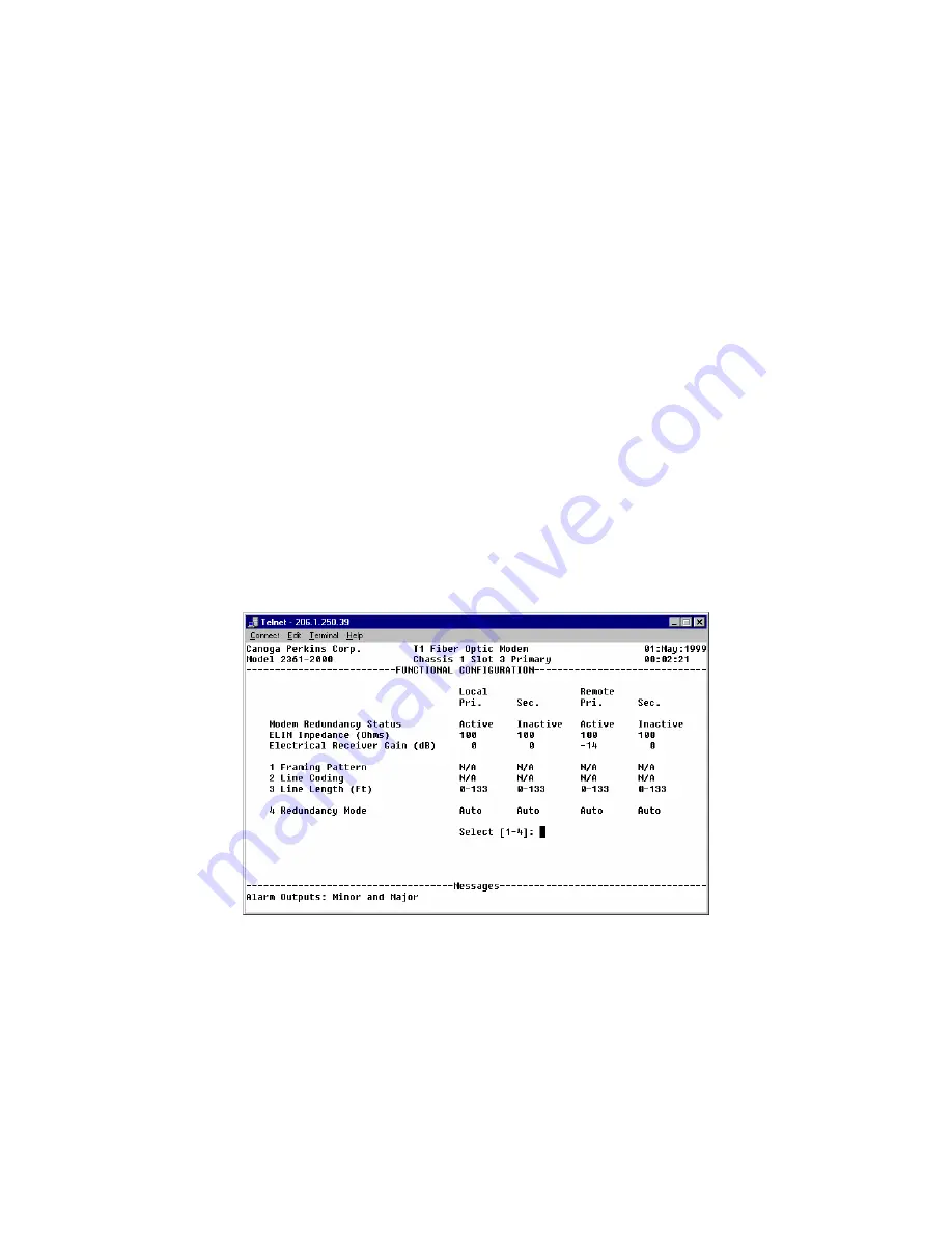
Figure 44. The Functional Configuration Screen
1.
From the 2361 Modem Main Menu, type "1." The System Configuration Screen appears.
2.
Type "2" to access the Functional Configuration menu.
3.
From that menu, type "4" to access Redundancy Mode options.
Summary of Contents for EdgeAccess Universal Chassis System 2361 T1
Page 1: ...2361 T1 Modem User Manual...


