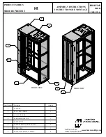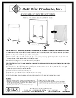
FIGURE #3
Placing Frames.
FIGURE #4
Installing Cross Braces.
FIGURE #5
Installing Back or Center Side Restraint Rails and Covers.
FIGURE #6
Installing Support Rails and Covers.
1
Initial Assembly:
Place frames over installed floor mounting hardware, finger tighten. See Figure #3. (Floor anchors are
not supplied with rack) All frames must be in the proper orientation as shown on the rack assembly drawing. Install back
(away from aisle) cross braces for single row rack and center braces for double row rack. See Figure #4. Please refer to
rack drawing for proper orientation of cross braces. Refer to Detail #1 for brace to frame installation and Detail #3 for
brace to brace connections.
ASSEMBLY INSTRUCTIONS:
2
Side Rails:
Install back side restraint rail for 2-tier racks and center side rails on 2-tier/2-row racks.
See Figure #5. Refer to Detail #2.
Place support rail(s) in location using supplied 3/8” bolt, lock washer and serrated strut nut. Ensure that the strut nut has
properly engaged the strut.
3
Installing Support Rails:
Install support rails from the back to front on 2-tier racks and from the center outward
on 2-tier/2-row racks. See Figure #6.
4
Leveling:
With all sup
and square. Shim fra
With all frames level a
Torque anchor bolts to
5
Install Inward Bracke
Install partially assem
location with hardware
exact location at a late
bracket may not be re
drawings. See Figure
Place front restraint
are in plac
6
Cell Installation Proc
and working out to ea
7
Battery Restraint Bra
tie rods and covers of
assembly. See Detail
installed before this st
covers will be very diff
8
Cell Installation Proc
oil, grease or any othe
for sliding batteries int
of water or unscented
friction on rail cover. P
polarities and termina
battery’s Installation a
Manual for more detai
back against the back
Repeat this procedure
tiers. Completely finish
starting the top row.
RSO1942 2/18/03 4:43 PM Page 2

