© 2017 United Technologies Corporation
1 / 4
P/N 3102475-EN • REV 001 • ISS 09NOV17
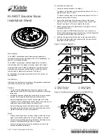
KI-ABST Sounder Base
Installation Sheet
Description
The KI-ABST sounder base adds alarm signaling capability to
compatible single-function smoke detectors. See “Specifications” on
page 3 for compatible detectors.
The KI-ABST sounder base is field-configurable for a low dB or
high dB output, and for a steady or temporal signal. See Figure 1.
In temporal mode, the KI-ABST generates the required fire alarm
signal and uses a separate synchronization module and polarity
reversal relay for signal synchronization. See Figure 4.
For application and programming details, refer to the control unit
documentation.
Installation
Install and wire this device in accordance with applicable national and
local codes, ordinances, and regulations.
Cautions
•
To prevent accidentally alarming the system, disconnect the
signaling line circuit (SLC) from the control unit before connecting
this device.
•
Electrical supervision requires that you break the wire run at each
terminal. Do not loop the field wires around the terminals.
•
Equipment damage hazard. Printed circuit boards are not field
repairable. When configuring the sounder base, make sure you are
cutting the correct location before you make the cut.
•
Equipment damage hazard. Overtightening the screw terminals
can damage the terminal and make wire connections less secure.
Tighten screws firmly, but do not overtighten.
Notes
•
Always connect the base to a steady voltage, whether the output
signal on the audible detector base is set to steady or temporal.
•
This device is prohibited from being installed in a dwelling unit as
defined in the National Building Code of Canada.
•
For determining where to locate the sounder base, refer to the
detector installation instructions.
To install the sounder base:
1. Configure the sounder base. See Figure 1.
To select a low dB output, cut the printed circuit board at J1. For a
high dB output, leave J1 intact.
To select a steady output, cut the printed circuit board at J2. For a
temporal output, leave J2 intact.
2. Connect the field wiring to the terminals. Observe the signal
polarity of the AUX riser (plus to minus and minus to plus). See
Figure 3 and Figure 4. Do not overtighten the screws.
3. Attach the base plate to the electrical box. See Figure 5. Do not
overtighten the screws.
If you are using the AB4G-SB surface mount box, make sure to
install a reinforcing plate at each knockout used. Reinforcing plates
are included with the AB4G-SB. See Figure 2.
4. Align the trim ring so that the four tabs on the ring mate with the
four slots in the base plate, and then press the trim ring onto the
base plate until the tabs lock.
Figure 1: Output configuration
(1) High dB, Temporal
(2) Low dB, Temporal
(3) High dB, Steady
(4) Low dB, Steady
Figure 2: Installing reinforcing plates on the AB4G-SB box
J1
J2
(1)
J1
J2
(2)
J1
J2
(3)
J1
J2
(4)

