43
6.4
LEAD LAG SETUP FOR UP TO 12
APPLIANCES
Honeywell SOLA can only support up to 8 boilers in a single
lead lag network, to sequence a second network of up to 12
boilers in total this will be activated through Pump C contact of
boiler #8.
Pump C is activated on a time delay algorithm where the timer
is initiated when boiler #8 begins the ignition sequence. The
delay timer is set based on the number of boilers in network
#1.
Pump C Delay Timer (Register #293) = Interstage Delay
(Default: 2 mins) x Number of Boilers. This delay timer will
allow all boilers in network 1 to perform an ignition attempt
before network 2 is initiated.
Due to the rotation of leaders in network 1; boiler #8 may
become lead boiler. Operation is not impacted regardless of
lead boiler in network 1 as all boilers in network 1 will attempt
to start before network #2 is initiated.
Network 2 operates independently of network 1 and as a result
the setpoint for network 2 is recommended to be set at least
2
o
F lower than network 1. A staggered setpoint approach will
reduce the amount of short cycling when all the boilers are
viewed as a complete system.
Network 2 can support up to a maximum of 4 boilers.
9 Boiler Outdoor Reset Wiring
The use of outdoor reset requires two outdoor sensors for this
setup. Network 1 outdoor sensor is wired to boiler #2 and the
outdoor sensor for boiler #9 requires the use of the outdoor
sensor module (PN: W8735S1000) wired to the ECOM
connection on the Honeywell SOLA.
Additional details can be found on page 76.
10 to 12 Boiler Outdoor Reset Wiring
The use of outdoor reset requires two outdoor sensors for this
setup. Network 1 outdoor sensor is wired to boiler #2 and the
outdoor sensor for network 2 is wired to boiler #10 on the
System/OutD contacts in the junction box.
Additional details can be found on page 77.
6.5
LOCAL/REMOTE SWITCH
The local remote switch mounted inside the control box is
designed to deliver an enable signal either relying on an
external contact closure (Remote) or enabling the boiler locally
(local). When Remote is selected via the SPDT switch the
Remote Operator contacts in the junction box must be closed
to deliver an enable signal. When Local is selected via the
SPDT switch a constant enable signal is present. When
troubleshooting the Dynaforce® it is recommended to switch to
Local mode.
6.6
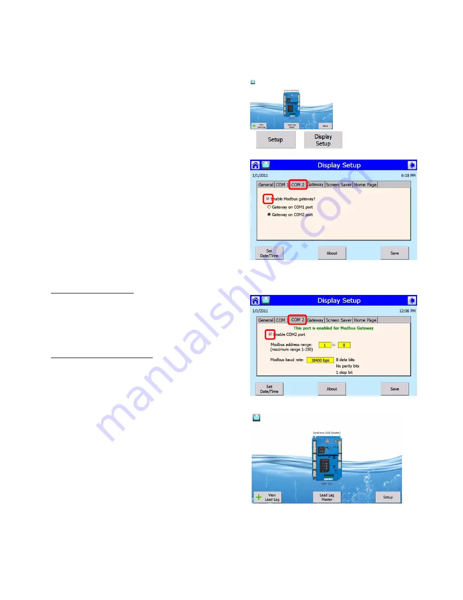
COMM. PORT 2 ACTIVATION
>
>
> Select Gateway tab
1)
Select Gateway tab
2)
Check Enable Modbus gateway
3)
Select Gateway on COM2 port
1) Select COM2 tab
2) Check Enable COM2 port
Summary of Contents for DRH300
Page 2: ......
Page 6: ......
Page 38: ...32 13 Place toggle switch setting to REMOTE for remote operation if required...
Page 69: ...63 PART 12 EXPLODED VIEW 19 1 2 3 4 5 6 7 8 9 10 11 12 13 14 15 16 17 18 20...
Page 70: ...64 21 22 23 24 26 35 34 33 32 31 30 29 28 27 25 36 37 38 39 40 42 43 56...
Page 77: ...71 PART 13 ELECTRICAL DIAGRAMS...
Page 78: ...72...
Page 79: ...73...
Page 81: ...75...
Page 82: ...76...
Page 83: ...77...
Page 86: ......


