SECTION 4. SENSOR INSTALLATION
4-7
4.13 TEXAS ELECTRONICS TIPPING
BUCKET RAIN GAGES (TE525,
TE525WS, TE525MM)
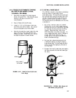
1. Mount the rain gage to a vertical pipe as
shown in Figure 4.13-1. Mounting the gage
directly to the tripod or tower is not
recommended.
2. Dig a 6" diameter hole 24" deep.
3. Center a 1 1/4" to 2" IPS pipe in the hole
and fill the hole with concrete. Use a level
to plumb the pipe as the hole is filled.
4. After the concrete has cured, attach the rain
gage to the top of the pipe with the hose
clamps provided. Route the sensor lead to
the tripod in plastic or metal conduit.
FIGURE 4.13-1. TE525 Texas Electronics
Rain Gage
4.14 CS700-L RAIN GAGE
The CS700-L should be mounted in a relatively
level spot that is representative of the
surrounding area. The lip of the funnel should
be horizontal and at least 30 inches above the
ground. The ground surface around the rain
gage should be natural vegetation or gravel.
The gage should not be installed over concrete
or pavement.
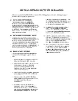
1. Mount the CS700 to either the CM100
(Figure 4.14-1) or a user supplied bracket.
Remove the CS700-L funnel from the base
by removing the three screws and lifting
upward. Adjust the three nuts on the
CM100 bracket to level the rain gage. On
user supplied brackets, shims or washers
can be used to level the rain gage. A
bubble level is mounted on the CS700-L
base to facilitate leveling.
2. Remove the rubber shipping band and
cardboard packing securing the tipping
bucket assembly. Tip the bucket several
times to insure the tipping mechanism is
moving freely.
3. Replace the housing assembly and tighten
the three screws to secure the housing to
the base.
FIGURE 4.14-1. CS700-L Rain Gage and
CM100 Mounting Bracket
TE525
Hose Clamp
(2) Places
CS700
CM100


