4-1
SECTION 4. SENSOR INSTALLATION
Sensor leads should be routed down the North side of the mast to the enclosure and secured with cable
ties.
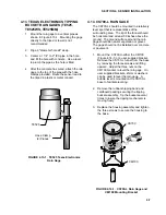
4.1 034A MET ONE WINDSET
Mount the 034A to the 019ALU crossarm as
shown in Figure 4.1-1.
1. Place the 034A stem and bushing into the
3/4" x 1” NU-RAIL fitting.
2. With the shoulder screw in place, orient the
counter weight to point due south. See
Section 4.19 for final calibration.
3. Tighten the NU-RAIL set screws and
remove the shoulder screw.
N
FIGURE 4.1-1. Met One 034A Wind Speed
and Direction Sensor
4.2 014A MET ONE WIND SPEED
SENSOR
Mount the 014A sensor to the 019ALU
crossarm as shown in Figure 4.2-1.
1. Insert the base of the sensor through the
3/4" NU-RAIL. Position the sensor 1" below
the NU-RAIL and tighten the set screws.
2. Connect the sensor lead to the sensor. A
small amount of lithium grease applied to
the threads of the connector will prevent
problems due to corrosion.
REGCOMENDED
Feed
SENSORS
Portland
Or USA
Serial
27115
FIGURE 4.2-1. Met One 014A Wind
Speed Sensor
014A
Shoulder
Screw
034A
Alignment
Screw
NU-RAIL
019ALU


