background image

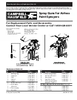
Airless Paint 
Sprayers

Please read and save these instructions. Read carefully before attempting to assemble, install, operate or maintain the product described.
Protect yourself and others by observing all safety information. Failure to comply with instructions could result in personal injury and/or prop-
erty damage! Retain instructions for future reference.

Assembly Instructions and Parts List

Airless Paint Sprayers

IN421000AV  3/02

BUILT TO LAST

Assembly Instructions

LIGHT DUTY CART MODELS

Tools required:

7/16” Wrench or 
adjustable

11/16” Wrench or 
adjustable

Hammer

1. Open packaging and check contents

against packing list on hardware pack.

2. Stand pump upright and hold steady.

Attach axle to cart legs by inserting
pre-assembled bolts into holes in cart
legs. Secure with one 1/4” - 20 nut on
each bolt. Use 7/16” wrench to tight-
en (See Figure 1).

3. Slide one 5/8” I.D. washer and wheel

on to each end of the axle. Using a
hammer, tap a pal nut onto each end
of the axle to retain the wheels (See
Figure 2).

4. Slide handle on to cart by depressing

the retaining snaps while pushing
handle in place. Be sure to check that

the retaining snaps lock into holes in
handle. Hose rack should be facing
the pump (See Figure 3).

5. Attach high pressure hose to pump

and spray gun using a 11/16” wrench
(See Figure 4). Do not attach suction
assembly at this time.

Assembly Instructions

HEAVY DUTY CART MODELS

1. Place washer from parts pack onto

axle.

2. Place wheel onto axle with side with

the longest hub going on first.

3. Place another washer on the axle.

4. Place cotter pin through hole in the

end of the axle.

5. Repeat for the other side (See

Figure 5).

6. Slide the two ends of the handle

over the two ends of the bottom
frame. The bend in the handle
should be away from the unit.

7. Stand behind the unit and reach

over the handle to grip the ends at
the bottom of the handle. Using
your thumb and forefinger, depress
the Valco Snaps and gently push
down on the handle until it starts
over the snaps. Then move your
hands to the top of the handle and
push it the rest of the way down
(See Figure 6).

8. When the handle is all the way

down the snaps will “click” into
place. If all four snaps do not pop
through, grasp the handle and twist
it right to left until the remaining
snap pops through.

CAM

PBE

LL

HAU

SFE

LD

Figure 1 - Attach Axle

Figure 2 - Attach Wheels

Figure 3 - Attach Handle

Figure 5 - Attach Wheels

Figure 4 - Attach Hose

Figure 6 - Attach Handle

Push

Lock

Push

Lock

For parts, product & service information

visit 

www.chpower.com

© 2002 Campbell Hausfeld/Scott Fetzer

Summary of Contents for LIGHT DUTY CART Airless Paint Sprayers

Page 1: ...hould be facing the pump See Figure 3 5 Attach high pressure hose to pump and spray gun using a 11 16 wrench See Figure 4 Do not attach suction assembly at this time Assembly Instructions HEAVY DUTY C...

Page 2: ...asket AL013702AV 1 34 Cast faceplate AL045102AV 1 35 Valve stem nut 3 pack AL083300AV 1 36 Gun swivel AL081300AV 1 37 Gun filter 100 mesh 2pack AL086101AJ 1 38 Trigger pin AL085800AV 1 39 Ball valve p...

Page 3: ...Please provide the following information Model number Serial number Part description and number as shown in parts list Address parts correspondence The Campbell Group Attn Parts Department 100 Product...

Page 4: ...15 42 GPM 49 42 26 100 015 48 50 GPM 55 50 31 150 017 60 GPM 55 60 43 200 019 Weight does not include mounting Specifications 4 www chpower com Eccentric Pressure Model Motor Kit Diaphragm Kit Bearing...

Page 5: ...s da pega O suporte da mangueira dever ficar vira do para a bomba ver Figura 3 5 Montar a mangueira de alta press o e pistola de pulveriza o bomba usando uma chave de 11 16 ver Figura 4 N o montar nes...

Page 6: ...rter Inclui 20 29 30 Ver esquema 1 32 Conjunto exc ntrico e chumaceira Ver esquema 1 33 Gaxeto do prato AL013702AV 1 34 Prato fundido AL045102AV 1 35 Porca do veio da v lvula pacote de 3 AL083300AV 1...

Page 7: ...27 25 23 22 21 20 32 3 PG Instru es de Montagem e Lista de Pe as Para Pe as de Substitu ao e Acess rios Contactar o seu Centro de Servi o Local ou Telefonar para 1 800 626 4401 PISTOLA DE CONSUMIDOR...

Page 8: ...e mangueira de pulveriza o 40 GPM 22 1 5 0 9 23 m 0 015 42 GPM 22 1 6 1 0 30 m 0 015 48 50 GPM 25 1 9 1 2 46 m 0 017 60 GPM 25 2 3 1 6 61 m 0 019 O peso n o inclui montagem Especifica es 4 PG PS A MC0...

Page 9: ...e de manguera debe estar de cara a la bomba vea Fig 3 5 Conecte la manguera de alta presi n a la bomba y a la pistola utilizando una llave de 11 16 pulg vea Fig 4 No conecte el conjunto de succi n en...

Page 10: ...uema 1 33 Junta de la placa de recubrimiento AL013702AV 1 34 Placa de recubrimiento fundida AL045102AV 1 35 Tuerca de v stago de bomba paquete de 3 AL083300AV 1 36 Dispositivo giratorio de pistola AL0...

Page 11: ...Montaje y Lista de Piezas Para piezas de repuesto y accesorios p ngase en contacto con su Centro de Servicio Local o llame al 1 800 626 4401 PISTOLA DOM STICA Por favor proporcione la siguiente inform...

Page 12: ...5 0 9 23 m 0 015 42 GPM 22 1 6 1 0 30 m 0 015 48 50 GPM 25 1 9 1 2 46 m 0 017 60 GPM 25 2 3 1 6 61 m 0 019 El peso no incluye soporte Especificaciones 4 ES Conjunto Conjunto Exc ntrica Conjunto de Mo...

Reviews: