background image

introduction

pressure Switch

 - ON/OFF Switch - In 

the ON position, the compressor shuts 
off automatically when tank pressure 
reaches the maximum preset pressure. 
In the OFF position, the compressor will 
not operate. This switch should be in 
the OFF position when connecting or 
disconnecting the power cord from the 
electrical outlet or when changing air 
tools.

regulator

 - The regulator controls the 

amount of air pressure released at the 
hose outlet.

aSMe Safety valve

 - This valve 

automatically releases air if the tank 
pressure exceeds the preset maximum.

exhaust tube

 - This tube carries 

compressed air from the pump to the 
check valve. This tube becomes very hot 
during use. To avoid the risk of severe 
burns, never touch the exhaust tube.

check valve

  - A one-way valve 

that allows air to enter the tank, but 
prevents air in the tank from flowing 
back into the compressor pump.

handle

 - Designed to move the 

compressor.

air outlet

 - A


quick connect coupler 

designed to work in combination with 
a quick connect plug to quickly and 
easily join a pneumatic tool to an air 
hose.

pressure Gauges

 - These gauges will 

show air pressure in the compressor 
tank and at the compressor outlet.

outlet pressure Gauge

 - Will show 

air pressure at the outlet in pounds per 
square inch (psi). Make sure this gauge 
reads ZERO (by adjusting regulator 
knob fully counterclockwise) before 
changing air tools or disconnecting air 
hose from outlet.

tank pressure Gauge

 - Will show air 

pressure in tank while the compressor 
is running, indicating compressor 
is building pressure properly. This 
gauge will show maximum pressure 
of compressor when it shuts off 
automatically at the pressure switch.

Drain valve

 - This valve is located 

underneath the tank. Use this valve to 
drain moisture from the tank daily to 
reduce the risk of corrosion.


Drain liquid from  

  tank daily.

Reduce tank pressure below 10 psi, 
then drain moisture from tank daily to 
avoid tank corrosion. Drain moisture 
from tank by opening the drain valve 
located underneath the tank.

installation

location

It is extremely important to install the 
compressor in a clean, well ventilated 
area where the surrounding air 
temperature will not be more than 
100°F.
A minimum clearance of 18 inches 
between the compressor and a wall is 
required because objects could obstruct 
air flow.


Do not locate the 

  compressor air inlet 

near steam, paint spray, sandblast areas 
or any other source of contamination. 
This debris will damage the motor

household use only. Store indoors.

electrical inStallation

 1.  Check and tighten all bolts, fittings, 

etc., before operating compressor.

 2.  Operate compressor in a ventilated 

area so that compressor may be 
properly cooled.

 3.  Compressor should be located 

where it can be directly plugged 
into an outlet, but if this is not 
possible, an extension cord may be 
used. It should be selected using the 
extension cord chart on page 5 as a 
guide.

 4.  To avoid loss of power and 

overheating, it is better to use 
additional air hose instead of 
extension cords to reach work area.
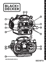
Figure 3

ASME Safety 
Valve

Pressure Switch

Tank Pressure 
Gauge

Outlet Pressure Gauge

Regulator

Air Outlet

4

Operating Instructions

www.chpower.com

Summary of Contents for HJ3001 Series

Page 1: ...s compressor pump is not equipped and should not be used as is to supply breathing quality air For any application of air for human consumption the air compressor pump will need to be fitted with suit...

Page 2: ...ay allow it to turn on inadvertently To prevent this and possible damage from power surge turn to OFF position after each use 8 Release all pressures within system slowly dust and debris may be harmfu...

Page 3: ...the spraying area as possible to minimize overspray accumulation on the compressor 5 When spraying or cleaning with solvents or toxic chemicals follow the instructions provided by the chemical manufac...

Page 4: ...essor is running indicating compressor is building pressure properly This gauge will show maximum pressure of compressor when it shuts off automatically at the pressure switch Drain Valve This valve i...

Page 5: ...hether the product is properly grounded Do not modify the plug provided if it does not fit the outlet have the proper outlet installed by a qualified technician This product is for use on a nominal 12...

Page 6: ...alve Do not remove or attempt to adjust the safety valve Check the safety valve by performing the following steps 1 Plug the compressor in and run until shut off pressure is reached see Operating Proc...

Page 7: ...en compressor shuts off 1 Loose connections fittings tubing etc 1 Check all connections with soap and water solution and tighten 2 Loose drain lock 2 Tighten 3 Check valve leaking 3 Disassemble check...

Page 8: ...sure switches e Drain cocks f Damage due to incorrect voltage or improper wiring g Other items not listed but considered general wear parts h Pressure switches air governors and safety valves modified...

Page 9: ...pas quip pour et ne devrait pas tre utilis comme soi pour fournir de l air respirable Pour les applications d air pour la consommation humaine il est n cessaire d quiper le compresseur d air pompe av...

Page 10: ...out signe de faiblesse ou d usure et assurer que tous les raccordements sont s rs ne pas utiliser si endommag Contacter un centre de service autoris pour l inspection ou la r paration Ne Pas faire fon...

Page 11: ...s inflammables 3 Utiliser un respirateur pendant la pulv risation 4 Ne pas diriger la peinture ou autre mat riel pulv ris vers le compresseur Situer le compresseur aussi loin que possible de l endroit...

Page 12: ...r servoir pendant le fonctionnement du compresseur ce qui confirme que le compresseur est en train d augmenter la pression de mani re appropri e Ce manom tre indique la pression maximum du compresseu...

Page 13: ...ant vert l ext rieur avec ou sans rayures jaunes est le fil de terre Ne pas utiliser d adaptateur de mise la terre avec ce produit Ne jamais connecter le fil vert ou vert et jaune une borne lectris Co...

Page 14: ...pression de sortie d passant la pression maximale indiqu e de l accessoire Cycle marche arr t du compresseur En position ON marche le compresseur pompe de l air dans le r servoir Lorsqu il atteint un...

Page 15: ...oteur du r servoir des canalisations d air et des ailettes de refroidissement de la pompe REMARQUE Il faut v rifier et nettoyer p riodiquement le filtre air dans le bo tier du filtre du c t de la t te...

Page 16: ...ibre dans la section de Installation 3 Clapet ou d chargeur d fectueux 3 Remplacer ou r parer Le protecteur de surcharge thermique se d clenche souvant 1 Tension basse 1 V rifier avec un voltm tre 2 F...

Page 17: ...17 Fr S rie HG3000 S rie HJ3001 S rie HJ3002 Notes...

Page 18: ...tallation de fils incorrecte g Autres articles pas indiqu s mais consid r s pi ces fatigue g n rales h Manostats r gulateurs d air et soupapes de s ret qui ont t s modifi s d apr s les r glages de l u...

Page 19: ...e compra con fecha para fines de la garant a Adj ntela a este manual o arch vela en lugar seguro IN634100AV 7 10 2010 Campbell Hausfeld Scott Fetzer Compresores de Aire Port tiles ASME de 13 79 bar Po...

Page 20: ...ver si est n deterioradas o hay fugas Antes de usarlo cerci rese de que las conecciones est n bien apretadas y no lo use si encuentra irregularidades Notif quele a un centro de servicio autorizado par...

Reviews: