background image

59

MC-III™ Panel Mount Flow Analyzer 

Section 4

K-Factor Entry

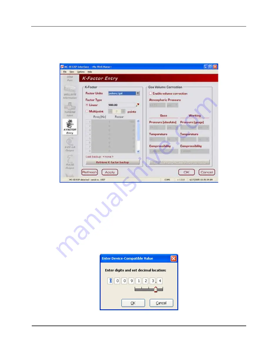
The K-Factor Entry screen (Figure 4.22) allows users to calibrate the MC-III Panel Mount using a single 

calibration factor from a turbine flow meter or multipoint linearization. Users can also configure the MC-III 

Panel Mount to compensate for the effect of pressure, temperature, and compressibility on gas volume.

Figure 4.22—K-Factor Entry screen

K-Factor Units

K-Factor entry consists of selecting the K-Factor unit and type (linear or multipoint). In selecting the unit, 

users can choose from five preprogrammed units (pulses per gallon, barrel, cubic meter, cubic foot, or liter). If 

a calculated divisor is to be used, “pulses per unit” should be selected.

K-Factor Type

For linear calibration, the user need only select the Linear checkbox and enter the K-factor of the turbine 

meter. To enter the K-factor value, click on the pencil icon to open a data-entry window (Figure 4.23). Enter 

the digits, left to right, and adjust the slide bar to move the decimal point to the proper position. 

Figure 4.23—Data-entry screen for linear K-factor

Summary of Contents for NUFLO MC-III

Page 1: ...NUFLO TM MC III Panel Mount Flow Analyzer User Manual Manual No 2350326 01 Rev 02 ...

Page 2: ...port Contact Information Cameron Measurement Systems Division 14450 John F Kennedy Blvd Houston TX 77032 Phone 1 800 654 3760 281 582 9500 Fax 281 582 9599 NuFlo and MC III are trademarks of Cameron International Corporation Cameron Modbus is a registered trademark of the Modbus Organization Inc Windows is a registered trademark of Microsoft Corporation Acrobat Reader is a registered trademark of ...

Page 3: ...les 14 Exporting Log Data 14 Saving Log Data in a Report 14 Section 2 Installation 15 Flow Meter Magnetic Pickup Installation 15 MC III Installation 15 Field Wiring Connections 17 Power Supply Wiring 18 Internal Power Supply 18 External Power Supply 18 Input Wiring 19 Turbine Flow Meter TFM Input 19 Pulse Input 19 Remote Reset Input 20 Output Wiring 21 Pulse Output 21 Analog 4 20 mA Rate Output 21...

Page 4: ...Date Synchronization 52 Contract Hour 52 LCD Contrast Adjustment 52 Security Setup 53 Firmware Version Number 53 Serial Number 53 Communications Port 54 Slave Address 54 Baud Rate 54 Bus Delay 55 Bus Timeout 55 Software Communication Options 55 Wellsite Information 56 Turbine Input 57 Volume Display 57 Rate Display 57 Input Type Sensitivity Configuration 58 Cut Off Thresholds 58 Calculation Period...

Page 5: ... 92 Appendix A Software Program Options A 1 General Options A 1 Autorun Options A 2 Communications Options A 3 Express Connect Option A 3 Auto Negotiate Option A 4 Enable Auto Negotiated Baud Rate Option A 4 Request to Send RTS Line Option A 4 Enable Modbus Address Support for Firmware Versions 1 06 through 1 08 A 4 Timing Parameters A 4 Downloading Options A 5 Advanced Options A 6 Clear EEPROM A ...

Page 6: ...Pointer Daily Event Pointer registers 17001 through 17006 C 11 Real Date registers 17007 17008 C 11 Real Time registers 17009 17010 C 12 Totals C 12 Pulse Output Pulses register 17077 C 12 Analog Output Current register 17079 C 12 Calculated K Factor register 17081 C 12 Holding Registers 32 bit Mode C 12 Control Register C 14 Wellsite Parameters C 15 Log Data C 15 Enron Registers C 16 Enron Hourly...

Page 7: ...The MC III s microprocessor circuitry counts the pulses generated by a companion flow meter converts that data into volume and rate values in accordance with calibration settings and displays the totalized data on a two line liquid crystal display LCD The eight digit top readout indicates total flow volume the six digit bottom readout indicates flow rate With the press of a single key totals are s...

Page 8: ... characters for easy to read prompts 0 3 character height Adjustable contrast and update period User selectable units of measurement Total Preprogrammed units BBL GAL LIT M3 CF SCF any unit x 1000 User defined units User selectable units of measurement Rate Preprogrammed units BBL GAL LIT M3 CF SCF per DAY HR MIN SEC any unit x 1000 per DAY HR MIN SEC User defined units Keypad 6 key membrane switc...

Page 9: ... bit and 32 bit holding registers For more information see Appendix C Enron Modbus Flow log parameters time stamp period total period run time and supply voltage and download method are Enron compatible System Requirements Operating System Windows 2000 or later Windows XP recommended Computer Processor 1 GHz or faster Pentium compatible CPU Memory 128 MB of RAM Hard Disk Space 21 MB for program fi...

Page 10: ...eprogrammed volume and time units in establishing the flow rate engineering unit for example gallons per hour gallons per day or gallons per minute Also the volume unit used for the flow rate can be different from the volume unit used to read Total volume The unit of measure for the Rate readout and the decimal point position are selected by the operator during calibration The daily index Day disp...

Page 11: ...el Mount keypad functions Interface Software Developed within the familiar Windows environment the MC III interface software is an intuitive and easy to use application that provides access to all controls for setting up and operating the instrument The interface tailors the controls to the user s needs providing three options for configuring the instrument a Configuration Wizard which steps throu...

Page 12: ... standard cubic feet SCF The MC III Panel Mount makes this process quick and easy by using fixed average values for the flowing gas temperature and flowing gas pressure See Gas Volume Correction Supercompressibility Calculation page 61 for more information Input Options The flow meter signal can be obtained from a magnetic pickup or a pre amplifier device The sensitivity of the flow meter input ma...

Page 13: ... the MC III Panel Mount are too numerous to mention some of the most commonly used functions are detailed in this section They include reading the rate and accumulated total saving totals to memory resetting the total viewing daily and hourly logs saving and uploading configuration files exporting log data to spreadsheet saving log data in a report Reading Totals Current totals can be viewed from ...

Page 14: ...ad by entering 02 2 Press UP ARROW TEST to increment the index 01 02 03 press LEFT ARROW LOG to decre ment the index 01 99 98 3 Press Enter Save to exit the Daily Volume Archive menu After 2 minutes of inactivity the Daily Vol ume Archive menu will time out and the total readout will be restored automatically Saving and Uploading Configuration Files The MC III interface software allows users to sa...

Page 15: ... If the connector is plastic apply grease only to the end that threads into the meter 3 Install the magnetic pickup in the flow meter 4 After the flow meter and magnetic pickup are installed in the flow line mount the MC III Panel Mount flow analyzer as described below MC III Installation The MC III mounts in a standard DIN square opening 3 62 X 3 62 in a vertical panel To install reference the di...

Page 16: ...16 Section 2 MC III Panel Mount Flow Analyzer SIDE VIEW TOP VIEW 3 10 78 74 STUDS 4 6 32 3 10 78 74 BETWEEN STUDS Figure 2 1 Typical mount dimensions in inches millimeters ...

Page 17: ...e 2 2 page 18 3 Connect the flow meter or pulse input wiring to terminal block TB1 See Figure 2 3 or Figure 2 4 page 19 4 Connect wiring for the remote reset input to terminal block TB1 if appropriate See Figure 2 5 or Figure 2 6 page 20 5 Connect wiring for output signals if appropriate See Figure 2 7 page 21 through Figure 2 12 page 24 6 Recalibrate the MC III Panel Mount if necessary 7 If exter...

Page 18: ... a remote power supply by a two conductor cable Figure 2 2 The power supply and cable must be capable of supplying 6 to 30 VDC 10 mA This capability is available only if the 4 20 mA rate output is not used External Power Supply The device will automatically switch to battery power when external power is lost It is recommended that the external power supply be an approved ELV source insulated from ...

Page 19: ...POWER TURBINE MAGNETIC PICKUP J1 J2 RESET SWITCH BATTERY A B Figure 2 3 Flow meter input wiring Pulse Input The pulse input provides an optically isolated input in systems where a preamplifier is inserted between the sensor and the MC III Panel Mount T B 3 TB1 PULSE INPUT RESET INPUT TFM A S GND EXT POWER 6 3 0 V D C J1 J2 RESET SWITCH BATTERY PULSE INPUT 3 TO 30 VDC Figure 2 4 Pulse input wiring ...

Page 20: ...witch in a remote location Figure 2 5 and with a pulse generator in a remote location Figure 2 6 The reset input or reset pulse must be active for 3 seconds to clear the total TB1 PULSE INPUT RESET INPUT TFM A S GND T B 3 EXT POWER 6 3 0 V D C J1 J2 RESET SWITCH BATTERY POWER SUPPLY 3 to 30 VDC Figure 2 5 Reset input wiring switch power supply TB1 PULSE INPUT RESET INPUT TFM A S GND T B 3 EXT POWE...

Page 21: ...lse output wiring Analog 4 20 mA Rate Output The 4 20 mA rate output provides a linear current output that represents flow rate This output requires a two conductor cable connected to an 8 to 30 VDC power supply voltage required is dependent on loop resistance and a current readout device located in the remote location The 4 20 mA rate output current loop also powers the MC III Panel Mount The int...

Page 22: ...e turbine meter frequency which may be used to provide flow rate and or total information to peripheral equipment The output requires a two conductor cable from the MC III Panel Mount to the remote frequency readout device requiring 50 mA or less and a 5 to 30 VDC power supply Figure 2 9 page 23 Caution The flow meter frequency output and 4 20 mA rate output are not isolated from each other and ca...

Page 23: ...r frequency amp square cannot be used simultaneously Figure 2 9 Flow meter frequency amp square output wiring RS 485 Output The RS 485 output is required for communication with the interface software Wiring diagrams are provided for a permanent connection Figure 2 10 as well as for temporary laptop connections using an RS 485 to RS 232 converter Figure 2 11 and Figure 2 12 page 24 A B TB1 PULSE IN...

Page 24: ...B TD A GND RS 232 9 PIN CONNECTOR Part No 101283116 TX TX Figure 2 11 RS 485 output connection to laptop with 9 pin converter TB1 PULSE INPUT RESET INPUT TFM A S GND T B 3 EXT POWER TB2 RS485 SLAVE 4 20 OUT PULSE OUT 6 3 0 V D C J1 J2 RESET SWITCH BATTERY B A GND RS 232 25 PIN CONNECTOR Part No 100025195 TX TX Figure 2 12 RS 485 output connection to laptop with 25 pin converter ...

Page 25: ...re used the MC III Panel Mount automatically calculates the divisor for volume calculation and the rate multiplier for flow rate calculation making calibration quick and easy Important For compensated gas measurement or gas or liquid measurement requiring multipoint 2 to 12 point linearization calibration must be performed with the software user inter face see Section 4 The following parameters ca...

Page 26: ... associated with the calibration factor typically pulses per gallon Press UP ARROW until the correct unit is displayed TEST Enter the decimal point position for the calibration factor Press LEFT ARROW to select the decimal point LOG 00000000 M3 BBL GAL LIT CF CF X1000 X1000 Press UP ARROW to change the position of the decimal point TEST Press LEFT ARROW to save the decimal point position and proce...

Page 27: ...U K FACTOR MENU Select no unit of measure Press UP ARROW until no unit is displayed as shown TEST 00000000 M 3 BBL GAL LIT CF CF X1000 X1000 Enter the decimal point position for the calculated divisor Press LEFT ARROW to select the decimal point LOG 00000000 M3 BBL GAL LIT CF CF X1000 X1000 Press UP ARROW to change the position of the decimal point TEST Press LEFT ARROW to save the decimal point p...

Page 28: ...vity of the MC III Panel Mount may be set to low medium or high when the input will be provided by a turbine flow meter If the input will be provided in the form of a pulse from a pre amplifier or other device rather than directly from a turbine flow meter the Pulse In pulse input setting in the Input Sensitivity menu should be selected See Section 2 for input wiring diagrams To Set Input Type and...

Page 29: ...To read the volume in terms of thousands of units ex 1 0 1 000 bbl continue pressing UP ARROW until both the unit of choice and the X1000 option are displayed TEST 00000000 000000 M 3 BBL GAL LIT M 3 BBL GAL LIT SEC MIN HR DAY CF CF X1000 X1000 STANDARD Enter the decimal point position Press LEFT ARROW three times or until the decimal point in the Total display begins blinking LOG 00000000 000000 ...

Page 30: ...ess flow rate Ex bbl in bbl day Press LEFT ARROW The volume unit of measure in the bottom portion of the LCD window should begin blinking LOG 00000000 000000 M 3 BBL GAL LIT M 3 BBL GAL LIT SEC MIN HR DAY CF CF X1000 X1000 STANDARD Press UP ARROW until the desired volume unit of measure is displayed Note If a calculated divisor was entered select user defined no units visible TEST Enter the time b...

Page 31: ...range within the range of the flow meter The low or zero setting is the flow rate value that will produce a 4 mA output The high or full scale setting is the flow rate value that will produce a 20 mA output Typically the high value is greater than the low value this scenario is defined as direct mode in Figure 3 1 Alternatively users may configure the 4 mA and 20 mA outputs to have an inverse rela...

Page 32: ...UT CURR MIN I I I RATE Low I High Low Where IOUT output current IMAX maximum current output 20 mA IMIN minimum current output 4 mA High programmed flow rate that produces a 20 mA output Low programmed flow rate that produces a 4 mA output RATECURR flow rate ...

Page 33: ...EFT ARROW to select the next digit to the left Continue pressing UP ARROW and LEFT ARROW alternately to enter all remaining digits LOG Press ENTER The LCD will display the High flow rate and the decimal point in the numeric display will begin blinking SAVE ENTER Enter the decimal point position for the High flow rate The words 4 20 mA HIGH should appear at the bottom of the LCD Press UP ARROW to c...

Page 34: ...T MENU Locate the Pulse Output setting Press ENTER repeatedly until the words Pulse Output appear in the lower display SAVE ENTER Enable or disable the pulse output Press UP ARROW to toggle output to on or off TEST Toggles between off and on Press ENTER If the pulse output is enabled the LCD will display Pulse Output Scaler and the decimal point in the numeric display will begin blinking SAVE ENTE...

Page 35: ...to 65535 excluding 252 to 255 and 64764 Press UP ARROW until the correct digit is displayed TEST Then press LEFT ARROW to select the next digit to the left Repeat using UP and LEFT arrows to enter all remaining digits LOG Press ENTER SAVE ENTER The Baud Rate menu prompt will appear immediately following the entry of the slave address See Entering the Baud Rate below for the baud rate entry procedu...

Page 36: ...36 Section 3 MC III Panel Mount Flow Analyzer ...

Page 37: ...re on a computer perform the following steps 1 Place the MC III CD in your CD ROM drive 2 The MC III install screen will load automatically 3 Click on Next to initiate the installation and follow the instructions on the screen An MC III icon Figure 4 1 will appear on the desktop of the user s PC or laptop when installation is complete To access the interface software click on the MC III icon on yo...

Page 38: ...MC III MC III The Welcome screen Figure 4 2 will appear and a Select COM Port window will prompt the user to select a communications port be used for connecting with the MC III Panel Mount Figure 4 2 2 Select a communications port from the dropdown list and click OK The software will attempt to con nect with the MC III Panel Mount via an RS 485 to RS 232 converter This automatic launch feature is ...

Page 39: ...s or upload previously saved configuration settings A checkbox at the bottom of the Device Autorun Options screen allows the user to bypass the Device Autorun Options screen and perform a selected function each time the software connects to the instrument Example To download all logs on connection select Download all logs from the Device Autorun Options screen and check the Always do checkbox Each...

Page 40: ...MC III interface software automatically attempts to connect to the instrument when a user clicks on the desktop application icon For more information on disabling the express connect feature and changing communications options see Appendix A Canceling Express Connect To temporarily cancel the express connect function without exiting the software program click in the LCD area of the device on the W...

Page 41: ...COM port setting click on Options Select COM Port Figure 4 7 and select the appropriate COM port from the list of ports detected Figure 4 7 COM port selection menu Software Connection in Multi Device Network In most cases the automatic launch or express connect feature is a convenient time saver However if multiple devices are daisy chained together in a network this feature can interfere with the...

Page 42: ...h The software will scan all addresses specified and display all instruments connected 7 Click on the appropriate address to connect to a device Important In daisy chain configurations verify that each device has a unique slave address Figure 4 8 Automatic detection of all connected devices A user who knows the address of a specific device may also connect to it by clicking File Connect Device at ...

Page 43: ...ach time a user change is made After downloading these logs from the instrument the instrument saves the data in a file By default the logs are saved as csv files The file format of the auto save flow log and event log files is user configurable Users can configure the software to download the auto save flow and event logs as Excel xls files by selecting Options Program Options Downloading from th...

Page 44: ...n screen Figure 4 12 page 45 gives users complete access to all configuration param eters The Advanced screen Figure 4 13 page 45 provides access to Modbus registers that can be modified to change configuration parameters recommended only for system configurators and host programmers If the desired configuration settings have been saved previously the configuration file can also be uploaded elimin...

Page 45: ... Mount Flow Analyzer Section 4 Figure 4 12 MC III Main configuration option for complete access to configurable parameters Figure 4 13 Advanced Access configuration option for system configurators and host programmers ...

Page 46: ...entered in the Calibration Wizard are written to the program Previous configuration settings are saved automatically in C NuFlo log data MC III Config Backup Files Using the Pencil Tool The data entry fields in the Configuration Wizard are highly intuitive and most can be completed by clicking in the field and entering new data or selecting a checkbox For data fields that require the user to enter...

Page 47: ... location Yes Step 5 Turbine Input 57 Rate Display units decimal location Yes Step 5 Turbine Input 57 Input Type Yes Step 3 Turbine Input 58 Input Sensitivity Yes Turbine Input 58 Input Cut off Thresholds Turbine Input 58 Calculation Period seconds Turbine Input 58 K Factor Yes Step 4 K Factor Entry 59 Multipoint K Factor K Factor Entry 59 Gas Volume Correction K Factor Entry 61 4 20 mA Output Yes...

Page 48: ...ument settings and the LCD displays will automatically update with each poll Live Updates Checkbox The Live Updates option is enabled by default However in the event that slow communication speeds are used or the system times out frequently the user can uncheck the Live Updates checkbox and periodically query the system by clicking on the LCD graphic on the Main screen Reset Flow Total Button The ...

Page 49: ...on allows the user to close out of a submenu screen without saving new settings and returns the user to the Main screen Pencil Tool for Data Entry The data entry fields in the MC III Main sub menu screens are highly intuitive and most can be completed by clicking in the field and entering new data or selecting a checkbox For data fields that require the user to enter a value such as a K factor and...

Page 50: ...50 Section 4 MC III Panel Mount Flow Analyzer Configuration Submenus MC III Main Wellsite Information System Setup Communications Port Turbine Input K Factor Entry 4 20 mA Output ...

Page 51: ...51 MC III Panel Mount Flow Analyzer Section 4 Configuration Submenus cont d Pulse Output Flow Archive Event Archive ...

Page 52: ...yed on the computer if the time difference exceeds 60 seconds To change the clock synchronization threshold to a value other than 60 seconds see General Options page A 1 A user can synchronize the instrument and computer clocks at any time by clicking the Sync to Computer Time button on the System Setup screen Contract Hour Hourly flow totals are logged in the archive on the hour The contract hour...

Page 53: ...rotection check the Keypad Lock checkbox on the System Setup screen and enter a four digit lock code in the field below the checkbox Do not use 0000 The security feature will be activated the next time a user attempts to access the keypad Firmware Version Number As firmware is upgraded firmware version numbers change The firmware version number shown may assist technical support personnel in troub...

Page 54: ...down keys on your computer keyboard If Modbus communication is not used leave the slave address at the factory setting 1 Baud Rate The baud rate is the number of bits per second that are on the serial port Baud rates supported by the MC III Panel Mount range from 300 to 115 2K This setting must match the setting of the master device polling the MC III Panel Mount or the serial port This only appli...

Page 55: ...cations Options screen Bus Delay Bus delay is the amount of time in milliseconds that passes before the MC III Panel Mount attempts to take control of the RS 485 bus and transmit a message back to the requesting device The MC III Panel Mount responds very quickly to incoming Modbus requests in some cases too quickly A configurable delay allows the user to control this response time A setting of 10...

Page 56: ...ll name and site location While most of the fields on this screen are optional a well name should be assigned The well name limited to 20 characters in length will also serve as the name of the folder where flow logs generated by the MC III software will be archived If a well name is not entered on this screen logs will be saved in a folder titled NO_WELLNAME Figure 4 20 Wellsite Information scree...

Page 57: ...ion see Entering a Calculated Divisor page 27 To display the volume in multiples of 1 000 units check the Multiplier checkbox Users can specify decimal point position from 0 1 to 0 0001 of a unit using the slide bar on the Turbine Input screen Important Before enabling or disabling the 1000 unit option for displaying flow totals clear the total display to zero If the total is not cleared the accum...

Page 58: ...only signals that exceed 40 mV peak to peak When a pulse input is selected no sensitivity setting is required Cut Off Thresholds Periods of very low or interrupted flow can lead to inaccuracies in indicated flow totals To help prevent these inaccuracies the user can establish cut off thresholds to determine the minimum frequency and or flow rate at which a signal will be recorded The flow rate cut...

Page 59: ...sists of selecting the K Factor unit and type linear or multipoint In selecting the unit users can choose from five preprogrammed units pulses per gallon barrel cubic meter cubic foot or liter If a calculated divisor is to be used pulses per unit should be selected K Factor Type For linear calibration the user need only select the Linear checkbox and enter the K factor of the turbine meter To ente...

Page 60: ...ile entering configuration parameters the user can restore the last saved set of configuration settings to the instrument Figure 4 24 Prompt to copy previous calibration settings to backup Select yes to save the previous calibration factor to memory The date and time of this backup is displayed next to the Retrieve K Factor Backup button on the K Factor Entry screen Only the last saved backup can ...

Page 61: ...all other Gas Volume Correction data fields will be activated Figure 4 25 Figure 4 25 Gas volume correction settings on K Factor Entry screen Atmospheric pressure is set at 14 73 psia by default but can be adjusted to local conditions To compensate the gas measurement to standard conditions complete the following steps 1 Enter the atmospheric pressure 2 Enter the base pressure and unit The base pr...

Page 62: ...mpositions Figure 4 26 To automatically calculate the compressibility factor enter the gas composition and click on Calculate The software will calculate flowing gas compressibility in accordance with the AGA 8 detail method The K Factor Entry screen will reappear and the calculated super compressibility factor will be displayed Figure 4 26 Gas Composition screen ...

Page 63: ...flow rate Zero and full scale values can be configured to represent any flow rate range within the range of the flow meter A test mode function is also included allowing a user to calibrate and or verify the output received by an end device Figure 4 27 4 20 mA Output screen The low or zero setting is the flow rate value that will produce a 4 mA output The high or full scale setting is the flow rat...

Page 64: ... will result in an output of current between 4 mA and 20 mA according to the following calculation MAX MIN OUT CURR MIN I I I RATE Low I High Low Where IOUT output current IMAX maximum current output 20 mA IMIN minimum current output 4 mA High programmed flow rate that produces a 20 mA output Low programmed flow rate that produces a 4 mA output RATECURR flow rate ...

Page 65: ...ow Rate field and enter the high or full scale flow rate value that will produce a 20 mA output Adjust the decimal position if necessary using the slide bar A flow rate equal to or greater than this maximum setpoint will result in an output of 20 mA Figure 4 29 Data entry screen for 4 20 mA low and high values 4 20 mA Output Testing The MC III software allows users to test the 4 20 mA output by en...

Page 66: ...66 Section 4 MC III Panel Mount Flow Analyzer Figure 4 30 4 20 mA output test screen ...

Page 67: ...rm the following steps 1 Check the Enable checkbox 2 Enter the pulse duration value using the plus and minus buttons on the screen or the page up and page down keys on a computer keyboard The pulse length pulse width determines the length of each output pulse in milliseconds ms 3 Click on the pencil icon next to the scale field to open a data entry window Figure 4 32 and enter the scale factor Adj...

Page 68: ... flow rate can exceed the maximum flow rate for short periods without compromising the accuracy of the total represented by the pulse output Pulse Output Testing The MC III software allows users to test the pulse output by writing a value to the pulse accumulator Such tests can aid in troubleshooting problems with hardware compatibility threshold settings and pulse duration settings To use the tes...

Page 69: ... at 1 39 22 p m Saving a Configuration File To save current configuration settings for future reference perform the following steps 1 Select File Save Configuration File Figure 4 34 A Save MC3 Configuration File screen will appear prompting the user to save the file to the computer hard drive The default directory is C NuFlo log data MC III WELL NAME however the user can specify a new location if ...

Page 70: ...o the MC III Panel Mount 3 Click Upload a configuration Figure 4 37 page 71 and click Do It Now A Load MC3 Configu ration File window will appear Figure 4 38 page 71 displaying the contents of the configuration folder 4 Click on the appropriate well name folder select the configuration file of your choice and click Open A Progress window will appear momentarily followed by an Information window co...

Page 71: ...71 MC III Panel Mount Flow Analyzer Section 4 Figure 4 37 Upload a Configuration option Figure 4 38 Default directory for configuration files ...

Page 72: ...tant The Advanced Access option is not required for the routine operation of the MC III Panel Mount and novice users should not access this portion of the software unless instructed to do so by Cameron technical support personnel Data retrieved from the MC III Panel Mount while in Advanced access mode can be logged to a file by enabling the Automatically log data polls checkbox on the Advanced Opt...

Page 73: ...hooting operational issues A user can download logs from the Flow Archive and Event Archive screens as needed or configure the software to automatically download the logs upon connection with the instrument See Automating Functions on Software Startup page 39 for more information When the download all logs or download only new logs option is selected from the Device Autorun Options menu and the Al...

Page 74: ... check the XLS MS Excel File checkbox Figure 5 2 Figure 5 2 Log download options Log Directory and Filenames Auto save log files are saved in C NuFlo log data MC III WELL NAME The wellname folder will bear the well name that appears on the Wellsite Information screen If no well name is entered on this screen the folder will be named NO_WELLNAME Log filenames incorporate the serial number of the MC...

Page 75: ... screen or in a trend chart see Daily Trend and Hourly Trend tabs Figure 5 3 Flow Archive screen Downloading Flow Logs To download flow logs click the Download button on the Flow Archive screen and select either Download All Flow Logs or Download Only New Flow Logs Figure 5 4 page 76 Download Only New Flow Logs will display only flow logs that have been created since the last download was performe...

Page 76: ...76 Section 5 MC III Panel Mount Flow Analyzer Figure 5 4 Menu for downloading flow logs from the Flow Archive screen Figure 5 5 Downloaded flow logs tabular view ...

Page 77: ...e top of the screen Figure 5 6 The circle s snap function allows the user to pinpoint transitional points within the trend display the greater the zoom the more precise the navigation Important The interactive cursor cannot be turned off To zoom in left click and drag the mouse to the right and down To zoom out drag the mouse up and to the left To reposition the chart within the viewing window rig...

Page 78: ...igure 5 7 Print preview tabular view To save the report perform the following steps 1 Select File Save from the task bar Figure 5 8 page 79 A Save Report As window will open Fig ure 5 9 page 79 2 Enter a filename The filename extension will be rps 3 Click Save By default log archive reports are saved in C NuFlo log data MC III WELL NAME however the user can specify a new location if desired The we...

Page 79: ... a Saved Report To view a saved report perform the following steps 1 From the Flow Archive screen click Print Table or Print Chart for trend chart views in the upper right corner of the screen 2 Select File Load from the task bar at the top of the page Figure 5 10 page 80 A Load Report win dow will open Figure 5 11 page 80 ...

Page 80: ...alyzer 3 Click on the report you wish to view A preview of the report will appear in the right portion of the win dow 4 Click Open Figure 5 10 Menu for loading a saved report Figure 5 11 Load Report screen for viewing saved flow log reports ...

Page 81: ...ppears click Save By default exported logs are saved in C NuFlo log data MC III WELL NAME however the user can specify a new loca tion if desired Figure 5 13 page 82 The wellname folder will bear the well name that appears on the Wellsite Information screen If no well name is entered on this screen the folder will be named NO_WELLNAME Important Users can also specify the file format to be used for...

Page 82: ...e The Event Archive screen Figure 5 14 allows users to download view export and print up to 345 user event logs Event logs are generated to track user changes such as K Factor changes input setting changes power on and watch dog resets and the flow and frequency cut off settings Figure 5 14 Event Archive screen ...

Page 83: ... Figure 5 15 Download Only New Event Logs will display only flow logs that have been created since the last download was performed Tabular views of the archive record Figure 5 16 page 84 include a time stamp showing the exact time each log was recorded as well as the name of the register changed and the old and new values assigned to that register Figure 5 15 Menu for downloading event logs from E...

Page 84: ...saved in C NuFlo log data MC III WELL NAME however the user can specify a new location if desired The wellname folder will bear the well name that appears on the Wellsite Information screen If no well name is entered on this screen the folder will be named NO_WELLNAME The procedure for printing and saving an event log report is nearly identical to the procedure for printing and saving a flow log r...

Page 85: ...if desired The wellname folder will bear the well name that appears on the Wellsite Information screen If no well name is entered on this screen the folder will be named NO_WELLNAME Important Users can also specify the file format to be used for all auto save logs csv or xls To change the auto save format follow the procedure described in Downloading Options page A 5 Figure 5 17 Dropdown menu for ...

Page 86: ...86 Section 5 MC III Panel Mount Flow Analyzer ...

Page 87: ...a tion on lithium batteries in Appendix B of this manual Important Press the ENTER SAVE key on the keypad before replacing the lithium battery to save the accumulated total to nonvolatile memory Once the battery is replaced and power is restored to the unit the last saved accumulated total will be displayed in the LCD The lithium battery is secured with a velcro strap to a metal plate which is con...

Page 88: ...ement Reinstalling the Velcro Strap If the velcro strap becomes separated from the metal bracket use the following instructions to ensure a tight compact fit around the battery 1 Thread the velcro through the bracket with fuzzy side facing upward 2 Turn the bracket over and pull the velcro strap through the slot to form a loop to hold the battery 3 Insert the battery then pull the loose end of the...

Page 89: ...it assembly perform the following steps 1 Record the locations of all cable connections to the circuit assembly 2 Using a small standard blade screwdriver remove all wiring from terminal blocks TB1 TB2 and TB3 ensuring that all wiring that is connected to powered circuits is insulated with tape 3 Unplug the battery cable from connector J1 on the circuit assembly Figure 6 1 page 88 4 Using a flathe...

Page 90: ...properly disengaged the cable will release freely 7 Remove the new circuit assembly from any packaging and connect the ribbon cable of the keypad to con nector J3 on the LCD side of the circuit assembly as follows a Insert the end of the ribbon cable into the plastic clip b While holding the ribbon cable in place press the black plastic clip into the connector until it snaps 8 Reconnect the batter...

Page 91: ... erase all configuration settings and log data To clear the EEPROM choose Options Program Options from the menu bar select Advanced from the dropdown options list and click on the Clear EEPROM button Figure 6 5 Technical assistance is typically required for upgrading firmware Contact Cameron s Measurement Systems Division to arrange for an upgrade Clicking the Clear EEPROM button will delete all c...

Page 92: ...0 ft Cable Assembly with Weatherproof Adapter 1 9A 100079898 25 ft Cable Assembly with Weatherproof Adapter 1 9A 100079880 30 ft Cable Assembly with Weatherproof Adapter 1 9A 100005168 50 ft Cable Assembly with Weatherproof Adapter 1 9A 100079879 100 ft Cable Assembly with Weatherproof Adapter 1 9A 100005128 200 ft Cable Assembly with Weatherproof Adapter 1 9A 100079687 300 ft Cable Assembly with ...

Page 93: ...k with the time displayed on the user s computer The MC III Panel Mount includes a real time clock for timekeeping and log time stamps and the internal time and date is preset at the factory However if the factory set time and date are inaccurate for the user for example if the user is in a different time zone the program will automatically detect the difference between the device s internal time ...

Page 94: ...x actions including navigating to one of three configuration screens downloading flow and event logs and uploading a configuration file A checkbox at the bottom of the screen allows the user to automate the selected function each time the software connects to the instrument The Autorun Options screen in the Program Options menu allows a user to terminate all autorun functions or change the autorun...

Page 95: ...oftware automatically attempts to connect to the instrument when a user clicks on the desktop application icon This feature is controlled by the Always attempt Express Connect on program startup checkbox setting in the Communications Option screen Figure A 4 When multiple devices are daisy chained together in a network the express connect function can interfere with the user s ability to connect t...

Page 96: ...nsmitted and that the converter will not stall in a receive mode after a period of inactivity By default this option is enabled To disable the option deselect the checkbox and click OK Enable Modbus Address Support for Firmware Versions 1 06 through 1 08 Operators with MC III units programmed with firmware versions 1 06 through 1 08 must check the checkbox labeled Enable Modbus Address Support for...

Page 97: ...nded This extension can be advantageous when connecting to a slow computer Downloading Options The MC III Panel Mount automatically saves daily flow logs on the contract hour and hourly flow logs around the clock The instrument also automatically saves an event log each time a user change is made By default the logs are saved as csv files The Downloading Options screen allows a user to change the ...

Page 98: ... EEPROM button will delete all configuration settings and log records in the MC III Panel Mount memory Figure A 6 Menu for clearing EEPROMs and enabling automatic data logs Automatic Data Logging Data retrieved from the MC III Panel Mount while in Advanced access mode can be logged to a file by enabling the Automatically log data polls checkbox on the Advanced Options screen To specify the filenam...

Page 99: ...ies The internal compo nent thionyl chloride is hazardous under the criteria of the Federal OHSA Hazard Com munication Standard 29 CFR 1920 1200 Before shipping a lithium battery or equipment containing a lithium battery verify that the packaging and labeling conforms with the latest version of all applicable regulations The transport of the lithium batteries is regulated by the United Nations Mod...

Page 100: ...B 2 Appendix B MC III Panel Mount Flow Analyzer ...

Page 101: ...upported by the MC III are as follows Function Code Hex Description 03 Read Holding Registers 05 Preset Boolean for Enron event record acknowledgement 10 Preset Multiple Registers For the read holding and preset multiple registers the instrument supports the full 250 bytes of data in a message This corresponds to 125 registers in 16 bit holding register size and 62 registers in 32 bit holding regi...

Page 102: ...emented as 5 Packed ASCII registers Here is an example of a well name that contains the string Test Well 413 Register Hexadecimal ASCII Characters 210 54 65 Te 211 73 74 St 212 20 57 SPACE W 213 65 6C el 214 6C 20 l SPACE 215 34 31 41 216 33 FF 3 UNUSED Unused characters at the end of each string will report 0xFF hexadecimal Registers Each register has an Access type read only or read write as des...

Page 103: ...value divided by 100 Example 100 Version 1 00 U16 RO 1003 03EB Manufacture Date MMYY U16 RO 1004 03EC Sales Date MMYY U16 RO 1005 03ED Serial Number 1 U16 RO 1006 03EE Serial Number 2 U16 RO 1007 03EF Power Mode 0 High Power 1 Low Power U16 R W 1 1008 03F0 Internal System Sample Rate Number of seconds to measure temperature and battery voltage U16 R W 3600 1009 03F1 Slave Address 1 65535 not inclu...

Page 104: ...ers 1003 1004 These parameters are set at the factory and are read only These registers are formatted as MMYY For example a value of 0905 represents the date September 2005 Slave Address register 1009 The Modbus slave address is an unsigned word U16 data type that has a range of values from 1 to 65535 not including 252 through 255 or 64764 The slave address is configured from a laptop or via the k...

Page 105: ...ne message The time and date can also be read in the holding register groups as floating point data Input Configuration Register Decimal Register Hex Description Data Type Access Default 2000 07D0 Volume Units Units 0 No Units 1 Gallons 2 Barrels 3 Cubic Meters 4 Cubic Feet 5 Liters Units 1000 16 No Units 17 Gallons 18 Barrels 19 Cubic Meters 20 Cubic Feet 21 Liters U16 R W 2 Standard Units 32 No ...

Page 106: ...rs 36 Cubic Feet 37 Liters Std Units 1000 48 No Units 49 Gallons 50 Barrels 51 Cubic Meters 52 Cubic Feet 53 Liters 2003 07D3 Rate Time Base 0 Second 1 Minute 2 Hour 3 Day U16 R W 3 2004 07D4 Rate Decimal Point Location 0 No digits to the right of the decimal point 1 Tenths 2 Hundredths 3 Thousandths U16 R W 2 2005 07D5 Calculation Period sec U16 R W 4 2006 07D6 Turbine Meter Input Configuration 0...

Page 107: ...ation Frequency 7 Hz FP R W 1 00 2025 07E9 Calibration Frequency 8 Hz FP R W 1 00 2027 07EB Calibration Frequency 9 Hz FP R W 1 00 2029 07ED Calibration Frequency 10 Hz FP R W 1 00 2031 07EF Calibration Frequency 11 Hz FP R W 1 00 2033 07F1 Calibration Frequency 12 Hz FP R W 1 00 2035 07F3 Calibration Factor 1 pulses per configured factor unit FP R W 900 00 2037 07F5 Calibration Factor 2 pulses pe...

Page 108: ...es to the instrument Therefore Calibration Frequency 1 should be the smallest of all calibration frequencies Output Configuration Register Decimal Register Hex Description Data Type Access Default 4000 0FA0 Pulse Output Source 0 Test Mode Disabled 1 Enabled U16 R W 0 4001 0FA1 Pulse Output Duration time is register value multiplied by 10 ms U16 R W 10 100 mS 4002 0FA2 Pulse Output Decimal Point Lo...

Page 109: ... 8016 4279 1F50 Daily Run Time seconds FP RO 17019 8018 427B 1F52 Hourly Total in terms of configured volume units FP RO 17021 8020 427D 1F54 Hourly Run Time seconds FP RO 17023 8022 427F 1F56 Polling Total in terms of configured volume units FP RO 17025 8024 4281 1F58 Polling Run Time seconds FP RO 17027 8026 4283 1F5A Previous Day Total in terms of configured volume units FP RO 17029 8028 4285 1...

Page 110: ...1 1F78 Hourly Run Time seconds FP RO 17059 8058 42A3 1F7A Polling Total base unit FP RO 17061 8060 42A5 1F7C Polling Run Time seconds FP RO 17063 8062 42A7 1F7E Previous Day base unit FP RO 17065 8064 42A9 1F80 Previous Day Run Time seconds FP RO 17067 8066 42AB 1F82 Previous Hour base unit FP RO 17069 8068 42AD 1F84 Previous Hour Run Time seconds FP RO 17071 8070 42AF 1F86 Previous Polling Total ...

Page 111: ...d in gallons To convert gallons to another unit of measure use the conversion factors listed in the table below For example to convert gallons to barrels multiply gallons times 0 02380952381 To Convert From Gallons To Multiply By No units 1 00000000000 Barrels 0 02380952381 Cubic meters 0 00378541178 Cubic feet 0 13368055556 Liters 3 78541178400 Polling Registers The MC III device stores the volum...

Page 112: ... Testing page 68 Analog Output Current register 17079 When the analog output is enabled see Analog Output Source register 4005 this register indicates the calculated output current based on the low and high values and the instantaneous flow rate When the analog output is disabled a user can use this register to write a desired output current for use in testing end devices Users can also perform th...

Page 113: ...s of configured volume units FP32 RO 7012 1B64 Polling Run Time seconds FP32 RO 7013 1B65 Previous Day Total in terms of configured volume units FP32 RO 7014 1B66 Previous Day Run Time seconds FP32 RO 7015 1B67 Previous Hour Total in terms of configured volume units FP32 RO 7016 1B68 Previous Hour Run Time seconds FP32 RO 7017 1B69 Previous Polling Total in terms of configured volume units FP32 RO...

Page 114: ...Day base unit FP32 RO 7032 1B78 Previous Day Run Time seconds FP32 RO 7033 1B79 Previous Hour base unit FP32 RO 7034 1B7A Previous Hour Run Time seconds FP32 RO 7035 1B7B Previous Polling Total base unit FP32 RO 7036 1B7C Previous Polling Run Time seconds FP32 RO 7037 1B7D Polling Index 0 65535 FP32 RO 7038 1B7E Pulse Output Pulses FP32 R W 7039 1B7F Analog Output Current FP32 R W 7040 1B80 Calcul...

Page 115: ...rs PA RO 400 0190 Sensor Model Number 20 characters PA RO 410 019A Sensor Serial Number 20 characters PA RO 420 01A4 Measurement Type 20 characters PA RO 500 01F4 User Note 64 characters PA RO These registers provide access to the ASCII characters that are used in the Wellsite Information screen of the software These registers are read only if these parameters need to be changed the user must use ...

Page 116: ...n Modbus Daily Log Refer to Enron Hourly Daily Record Format RO 7000 1B58 Hourly Pointer 1 to 768 FP32 RO 7001 1B59 Daily Pointer 1 to 384 FP32 RO 7002 1B5A Event Counter 1 to 345 FP32 RO Enron Hourly Daily Record Format Parameter Data Type Date MMDDYY FP32 Time HH MM SS FP32 Total base units FP32 Flow Time number of seconds of flow FP32 Supply Voltage VDC FP32 Enron Event Record Format Parameter ...

Page 117: ...ue used to indicate the reset source in the event log The following table indicates the reset status Reset Status Status Code Value Normal 0 Power On Reset 3 Watch Dog 8 Software Reset 16 Flash Memory Error 32 Log Capacity Log Type Capacity Hourly Logs 768 Daily Logs 384 Event Logs 345 ...

Page 118: ...C 18 Appendix C MC III Panel Mount Flow Analyzer ...

Page 119: ...C 19 MC III Panel Mount Flow Analyzer Appendix C ...

Page 120: ...R U S S I A 603 5569 0501 ms kl c a m com ...

Reviews: