E N G I N E E R E D & P R O C E S S V A L V E S
07/2011 / IOM-GEN-TWIN-03
15
Installation, Operation and Maintenance Manual
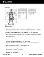
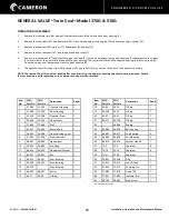
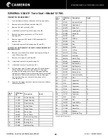
OPERATOR DISASSEMBLY
1.
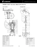
Remove the indicator pin (34) and pull the indicator stem (8) up through the gear housing (2).
2.
Remove the stop screw (35) and dowel pin (33). Drive out the upper coupling pin (32) and remove the coupling (10).
3.
Remove the capscrew (29), washer (11), handwheel (9) and key (12).
4.
Remove the four capscrews (27) and the gear housing cover (7).
5.
Remove four capscrews (27) and lift off the gear housing (2). It may be necessary to turn the worm shaft counterclockwise to back
the worm clear of the gear while lifting off the gear housing. The worm shaft (6) and the tapered bearing cup (24) and cone (25)
on each end may now be removed from the gear housing (2).
6.
The operator stem (3), upper stem (4), bearings (23), and roller (16) may now be lifted out of the operator housing.
NOTE: The cam bushing (13) and stem bushing (14) are a press fit in the operator housing and should not be removed. Should
the cam bushing require replacement, the operator housing must be returned.
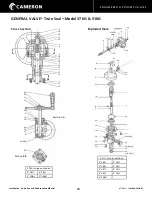
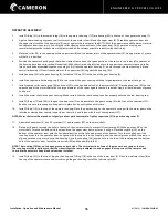
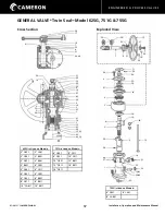
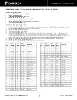
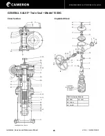
GENERAL VALVE
®
Twin Seal
™
Model 376G & 510G
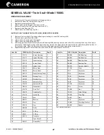
Item
No.
376G
Part No.
501G
Part No.
Description
Req’d
1
21-583
21-555
Operator Housing
1
2
21-584
21-554
Gear Housing
1
3
22-524
22-508
Operator Stem
1
4
23-560
23-525
Upper Stem
1
5
77-465
77-464
Pin*
1
6
24-451
24-445
Worm Shaft
1
7
26-632
26-580
Gear Housing Cover
1
8
27-545
27-504
Stem Indicator
1
9
28-441
28-442
Handwheel
1
10
32-476
32-469
Coupling
1
11
44-465
44-453
Handwheel Washer
1
12
45-431
45-431
Key
1
13
46-557
46-501
Cam Bushing
1
14
46-558
46-502
Stem Bushing
1
15
46-559
-
Pilot Bushing
1
16
48-405
48-401
Roller
1
17
62-71
62-34
O-Ring
1
Item
No.
376G
Part No.
501G
Part No
Description
Req’d
18
62-83
62-70
O-Ring
1
19
62-398
62-79
O-Ring
1
20
62-91
62-91
O-Ring
1
21
62-371
62-339
O-Ring
2
22
-
64-424
Caplug
23
66-483
66-476
Ball bearing
2
24
66-481
66-477
Cup Bearing
2
25
66-482
66-478
Cone Bearing
2
26
69-414
69-414
Spinner Handle
1
27
72-5
72-5
Capscrew
8
28
72-16
72-10
Capscrew
4
29
72-21
72-26
Capscrew
1
30
76-891
76-594
Plug
1
31
76-612
76-612
Lube Fitting
1
32
77-422
77-417
Coupling Pin
2
33
77-480
77-418
Dowel Pin
1
34
77-451
77-440
Indicator Pin
1
35
98-790
98-663
Stop Screw
1
* not available separately.

