background image

E N G I N E E R E D   &   P R O C E S S   V A L V E S

07/2011  /  IOM-GEN-TWIN-03

11

Installation, Operation and Maintenance Manual

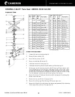
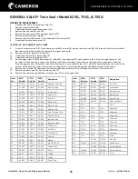
GENERAL VALVE

®

 Twin Seal

™ 

MODEL 375H

Item 
No.

375 H 
Part No.

Description

Req’d

1

21-419

Operator Housing

1

2

22-417

Upper Stem

1

3

22-418

Lower Stem

1

4

27-418

Indicator Shaft

1

5

27-419

Indicator Flag

1

6

28-406

Handwheel

1

7

45-411

Key

1

8

46-425

Bushing

1

9

48-405

Roller

1

10

50-402

Grease Retainer

1

11

62-32

O-Ring

1

12

64-415

Protector

1

13

64-417

Insignia Plate

1

14

65-402

Grease Seal

1

15

66-409

Ball Bearing

1

16

72-5

Capscrew

4

17

74-6

Screw

1

18

74-9

Set Screw

1

19

75-434

Nut

1

20

76-411

Lube Fitting

1

21

77-407

Guide Pin

1

22

77-423

Drive Pin*

1

23

77-453

Roll Pin

1

24

78-413

Retaining Ring

1

25

78-414

Retaining Ring

1

375 H is Used on Models:

2”

C811

2”

C821

3”

CA811

3”

CA821

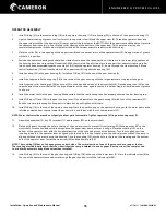
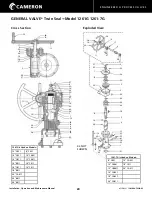
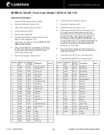
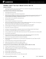
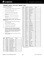
OPERATOR DISASSEMBLY

1.  

Unscrew (17) and remove indicator flag (5).

2.  

Remove the stem protector (12).

3.  

Remove the handwheel nut (19), 


handwheel (6), key (7) and grease 


retainer ring (10).

4.  

Remove the retainer ring (25) and pull out  


the upper stem (2) with lower stem (3),    


bearing (15), roller (9) and indicator shaft  


subassembly (4) out through the top of 


the housing (1).

5.  

Remove set screw (18) from bottom of    


lower stem and push indicator shaft sub-   


assembly (4) out through the bottom of    


the lower stem.

6.  

Separate the stems and remove the 


retaining ring (24) and the bearing (15)    


from the upper stem.

7.  

Remove grease seal (14) and bushing (8)


(if required) from top of upper stem (2).

8.  

Remove O-Ring (11) from inside housing

.

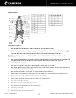
OPERATOR ASSEMBLY

1.  

Install O-Ring (11) in housing (1).

2.  

Place the bearing (15) on the top of the    


upper stem (2). Install retaining ring (24).

3.  

Apply a liberal coating of grease to all


surfaces of upper stem (2) and inside and   


outside of lower stem (3).

4.  

Thread the upper stem and lower stem 


together such that the drive pin (22) in the  


upper stem comes against the shoulder at


the TOP of the lower stem (3) and the  


detent recess in the upper stem is exactly in  


line with roller opening in the lower stem.


NOTE: This operation may require several


attempts as the threads are multiple start


and do not always assemble correctly with


the first try.

5.  

Install the indicator shaft sub-assembly (4)  


up through both stems. Align the detent   


hole in the indicator disc with the threaded  


hole in the lower stem and fasten with    


set screw (18). Set screw must be below the  


outside surface of the lower stem.

6.  

Place the roller (9) in the side opening of   


the lower stem. A liberal application of    


grease will hold the roller in position.

7.  

Place the stem assembly into the housing


taking care that roller is aligned with roller


groove in housing. Push the entire 


assembly down until the bearing rests on   


the shoulder in the housing.

8.  

Install the retaining ring (25) in the top of  


the housing (1).

9.  

Install grease retainer (10) in handwheel (6)


and place handwheel and key (7) on upper


stem. Install bushing (8) and grease seal    


(14) in handwheel nut (19). Screw the nut  


on the upper stem and tighten down on   


handwheel securely.

10.   Install stem protector (12).
11.   Install indicator flag (5) and secure 
 

      with screw(17).


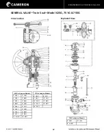
Cross Section

19

17

20

25

15

22

9

18
21

4

5

12

14
8

6

10

24

7

2

3

1

16

23

13

11

17

5

12

4

19
7
25

10

24

15
22
9
1
2
3

18
21

16

5
8

6

11

Exploded View

* not available separately.

Summary of Contents for GENERAL VALVE Twin Seal 400 Series

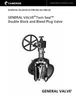
Page 1: ...ENGINEERED PROCESS VALVES GENERAL VALVE Twin Seal Double Block and Bleed Plug Valve GENERAL VALVE Installation Operation and Maintenance Manual ...

Page 2: ...ENGINEERED PROCESS VALVES 2 07 2011 IOM GEN TWIN 03 Installation Operation and Maintenance Manual ...

Page 3: ... Bolted Gland 6 Bushings One Gland 7 Bushings Two Gland 7 Bearings Duel Retention 8 Bearings Internally Externally Retained 9 Bearings Internal Retained with Two Glands 9 Series 8800 10 Operators Model 375H 11 Model 500H 625H 12 Model 376G 501G 14 Model 625G 751G 755G 17 Model 1261G 1261 7G 20 Model 1276G 23 Model 1500G 26 Bleeds The DTR System Explained 29 Miscellaneous Operation Maintenance 31 P...

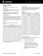
Page 4: ...ified minimum amount of clearance will make servicing easier Flange Fasteners Certain Twin Seal flange holes are drilled and tapped when there is no possibility of fitting a hexagonal nut behind the flange The quantity and size of these tapped holes is shown in Table 2 Capscrews or stud bolts may be used in these holes TABLE 2 Valve Size inch ASME Class 150 Number of Tapped Holes per Flange Thread...

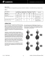
Page 5: ...ions Only after the slips are fully retracted perpen dicularly from the body seat is the plug rotated to the open position Conversely in closing the valve the plug and slips are rotated freely with no seal to body contact until the slips are positioned over the ports Then the plug is driven down between the slips and the tapered surfaces wedge out the slips for a positive upstream as well as downs...

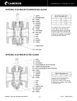
Page 6: ...smallest of the Twin Seal valves do not require discrete bushings due to minimal hydro seating forces within the valve Also note that due to the size of the operator the gland is held in by a retaining ring backed up by the operator housing Typical Arrangement of 4 C811 The units do not require discrete bushings due to small hydro seating forces and by incorporating a slightly larger operator a bo...

Page 7: ...orces which in turn requires two glands Typical Arrangement of 2 C841 6 C911 12 C811 2 C851 6 C921 12 C821 2 C861 6 C941 12 A1911 2 C911 8 C411 12 C921 2 C921 8 C421 14 C811 2 C941 8 C811 14 C821 3 C841 8 C821 14 C911 3 C911 8 C841 16 C411 4 C821 8 C911 16 C811 4 C841 8 C921 16 C821 4 C911 10 C411 16 C911 21 4 C921 10 C421 18 C411 4 C941 10 CA811 18 C811 6 C411 10 C821 20 C411 6 C421 10 C911 20 C4...

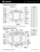
Page 8: ... C941 14 C841 16 C921 18 CA821 18 C911 20 CA821 20 CA841 20 C841 20 CA911 20 CA921 24 CA811 24 C811 24 C821 24 CA821 24 C911 28 C811 28 CC821 30 CC811 30 C821 As valve size increases so does the plug load therefore these sizes require bearings Typical Arrangement of 36 CA811 This valve requires bearings The inner bearing retainer is slightly different than the one above ...

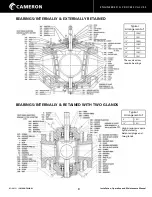
Page 9: ...NGS INTERNALLY EXTERNALLY RETAINED BEARINGS INTERNALLY RETAINED WITH TWO GLANDS Typical Arrangement of 10 CB841 10 C941 12 CB841 16 CA841 16 C941 20 CA921 24 C841 These valve sizes require bearings Typical Arrangement of 8 C851 10 C851 High pressures require hydrostatically balanced plugs and two glands ...

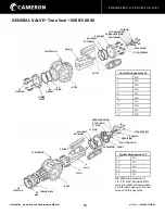
Page 10: ...eption of 14 20 24 Models 8811G remaining sizes all incorporate an internal coupling to connect valve with the operator 76 PIPE PLUG 4 PLUG 62 O RING 49 GASKET 2 BONNET 6 GLAND 77 LOCATING PIN 62B BACKUP RING 62A O RING 63 PACKING 72 CAP SCREW 5 SLIPS 1 BODY 62 O RING 49 GASKET 3 LOWER PLATE 76 PIPE PLUG 1 BODY 3 LOWER PLATE 75 NUT 76 PIPE PLUG 76 PIPE PLUG 5 SLIPS 62 O RING 49 GASKET 62B BACKUP R...

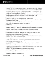
Page 11: ...O Ring 11 in housing 1 2 Place the bearing 15 on the top of the upper stem 2 Install retaining ring 24 3 Apply a liberal coating of grease to all surfaces of upper stem 2 and inside and outside of lower stem 3 4 Thread the upper stem and lower stem together such that the drive pin 22 in the upper stem comes against the shoulder at the TOP of the lower stem 3 and the detent recess in the upper stem...

Page 12: ... of the housing 1 If the bearing is snug in the housing replace the handwheel and key Turn the handwheel clockwise to raise the lower stem as far as possible Insert a 3 8 diameter bar through the two holes in the bottom of the housing Turn the handwheel clockwise and jack the bearing clear of the housing 8 Remove the set screw 16 and push the indicator shaft subassembly 7 out through the bottom of...

Page 13: ...ft assembly 7 up through both stems Align the detent hole in the indicator disc with the threaded hole in the lower stem and fasten with set screw 25 Set screw must be below the outside surface of the lower stem 4 Install O Ring 16 in housing 1 5 Place roller 14 in opening of lower stem A liberal application of grease will hold it in position 6 Place the stem assembly into the housing taking care ...

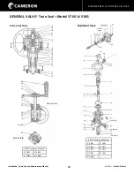
Page 14: ...1 G is Used on Models 2 C841 2 C921 3 C841 3 C911 4 C811 4 C911 4 C821 4 C921 6 CA811 8 34 18 21 23 2 9 4 19 27 16 13 5 14 21 3 32 10 1 27 15 26 29 11 12 28 7 17 20 24 25 31 6 24 444 30 Section B B Section A A Exploded View 29 11 9 11 49 648 020 7 6 20 17 12 24 26 25 PLASTIC SHIM 34 24 25 31 8 21 2 23 4 18 16 3 5 19 21 23 13 1 14 27 28 32 UPPER 30 33 35 22 32 LOWER 10 15 376 ONLY Cross Section ...

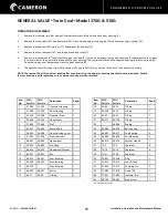
Page 15: ...operator housing must be returned GENERAL VALVE Twin Seal Model 376G 510G Item No 376G Part No 501G Part No Description Req d 1 21 583 21 555 Operator Housing 1 2 21 584 21 554 Gear Housing 1 3 22 524 22 508 Operator Stem 1 4 23 560 23 525 Upper Stem 1 5 77 465 77 464 Pin 1 6 24 451 24 445 Worm Shaft 1 7 26 632 26 580 Gear Housing Cover 1 8 27 545 27 504 Stem Indicator 1 9 28 441 28 442 Handwheel ...

Page 16: ... of grease to all parts 8 Install the worm shaft in the gear housing Make certain that the rear bearing cone has properly entered the rear bearing cup 9 Install O Rings 17 and 20 in the gear housing cover 7 and assemble to the gear housing 2 with four of the capscrews 27 Run the screws in just enough to keep parts in place but do not tighten at this time 10 Install O Ring 19 in the top of the oper...

Page 17: ...11 4 C841 6 C921 6 C821 6 8821 8 C811 8 8811 10 CA811 10 8811 751G is Used on Models 6 C841 8 C911 8 C821 10 C911 10 C821 12 8811 12 C811 14 8811 14 C811 755G is Used on Models 6 C851 8 C941 8 CA841 41 34 17 18 7 32 8 21 26 28 24 16 4 33 5 20 11 39 13 25 36 9 10 27 43 29 6 19 2 35 1 31 14 3 12 22 38 15 42 23 40 30 26 28 32 7 8 21 29 13 17 34 18 11 39 24 25 16 10 36 9 27 6 2 4 10 19 43 5 20 3 12 14...

Page 18: ...per stem 4 16 Remove the retaining ring 43 and lower bearing 27 from the upper stem Item No 625G Part No 751G Part No 755G Part No Description 1 21 422 21 623 21 623 Operator Housing 2 21 408 21 405 21 443 Gear Housing 3 22 440 22 555 22 555 Lower Stem 4 22 439 22 554 22 554 Upper Stem 5 41 406 41 401 41 401 Drive Pin 6 23 402 23 403 23 406 Worm Gear 7 24 404 24 404 24 403 Worm Shaft 8 26 401 26 4...

Page 19: ...ss of gear housing 2 with large diameter of taper facing out 11 Install tapered roller bearing cup 28 and cone 26 on handwheel end of worm shaft 7 Place bearing cone 26 on opposite end with large diameter of taper against shaft shoulder 12 Install worm shaft in gear housing Make certain that rear bearing cone has properly entered rear bearing cup 28 13 Install O Ring 21 in bearing cap 8 14 Apply a...

Page 20: ...911 18 8811 20 CA811 20 8811 24 8811 Exploded View 1261 7G is Used on Models 8 C851 12 CA921 10 CB841 18 C911 12 CB8411 20 CA911 16 CA821 18 CA821 24 CA811 29 17 6 11 34 16 30 8 28 39 28 27 2 28 27 37 8 22 10 24 33 7 15 25 2 18 35 40 26 3 1 12 32 13 4 21 41 14 23 11 31 19 36 42 38 5 30 8 17 6 28 27 20 28 27 29 16 34 11 37 22 7 15 9 33 24 25 39 5 2 39 40 26 26 18 3 4 13 32 23 41 14 35 1 21 12 19 38...

Page 21: ... O Ring 1 21 62 208 62 208 O Ring 1 22 64 411 64 411 Protector 1 23 64 416 64 416 Plastic Plug 2 10 Unbolt and remove the gear housing 2 11 Remove the retaining ring 40 12 Unbolt and remove the guide pin 13 13 Pull the upper stem 3 with the lower stem 4 roller 19 two bearings 26 and indicator shaft 10 out through the top of the housing 1 If the bearings are snug in the housing install the worm gea...

Page 22: ...tall tapered roller bearing cup 28 in rear bearing recess of gear housing 2 with large diameter of taper facing out 13 Install tapered roller bearing cup 28 and cone 27 on handwheel end of worm shaft 6 14 Install worm shaft 6 in gear housing 2 Make certain that rear bearing cone 27 has properly entered the rear bearing cup 28 15 Install O Ring 20 in bearing cap 8 16 Apply a smooth coating of Form ...

Page 23: ...6 C921 16 CA841 20 CB921 20 CA821 24 CA821 30 CC811 31 34 18 19 13 7 29 30 36 9 36 41 10 22 9 39 12 24 17 8 35 27 6 20 28 21 43 23 45 15 37 25 42 44 16 33 32 40 1 2 4 38 3 5 26 11 41 36 38 33 25 15 45 42 37 1 23 Exploded View Cross Section 11 35 8 27 9 39 24 26 17 6 3 30 29 7 19 30 29 41 31 18 34 22 10 13 21 14 36 49 649 20 SHIM NOT SHOWN 28 20 5 4 2 40 32 43 16 12 44 ...

Page 24: ... housing and remove the bearings with a suitable puller 13 Separate the upper and lower stems and remove indicator shaft assembly 12 Item No 1276G Part No Description Req d 1 21 594 Lower Housing 1 2 21 595 Upper Housing 1 3 21 505 Gear Housing 1 4 22 533 Lower Stem 1 5 22 534 Upper Stem 1 6 23 461 Worm Gear 1 7 24 425 Worm Shaft 1 8 26 487 Gear Housing Cover 1 9 26 488 Bearing Cap 1 10 26 489 Bea...

Page 25: ...ooth even coating of Form a Gasket to the surface of the guide pin boss on the lower housing 1 10 Insert the guide pin 16 to fully engage the slot in the lower stem and fasten with cap screws 33 11 Place the gear key 20 in the keyway of the upper stem 5 12 Place the tapered roller bearing cones 29 on each end of the worm shaft 7 with the large diameter of the cone taper against each shaft shoulder...

Page 26: ...on Exploded View Handwheel not shown 1500F is Used on Models 20 C841 16 C941 30 CC821 36 CA811 11 35 8 27 9 41 36 39 24 26 17 6 3 30 29 7 19 30 29 31 41 18 34 36 13 10 22 14 21 28 20 5 4 SHIELDS NOT SHOWN 25 93 424 25 93 492 10 22 30 29 7 9 36 34 31 18 19 41 19 21 42 2 11 39 24 26 8 35 39 40 6 27 38 28 2 5 1 32 40 16 33 4 44 23 12 43 15 45 46 37 ...

Page 27: ...rate the upper and lower stems and remove the nut 43 and indicator shaft 12 GENERAL VALVE Twin Seal Model 1500G Item No 1500G Part No Description Req d 27 66 424 Ball Bearing 1 28 66 425 Ball Bearing 1 29 66 454 Bearing Cone 2 30 66 463 Bearing Cup 2 31 69 414 Spinner Handle 1 32 71 109 Stud 12 33 72 5 Capscrew 2 34 72 8 Capscrew 1 35 72 26 Capscrew 8 36 72 64 Capscrew 12 37 73 87 Capscrew 12 38 7...

Page 28: ...e upper housing 9 Apply a smooth even coating of Form a Gasket to the surface of the guide pin boss on the lower housing 10 Insert the guide pin 16 to fully engage the slot in the lower stem and fasten with cap screws 33 11 Place the gear key 20 in the keyway of the upper stem 12 Place the tapered roller bearing cones 29 on each end of the worm shaft 7 with the large diameter of the cone taper aga...

Page 29: ...ressurizes the upstream throat of the valve The standard relief valve is set to open at 25 psi on all valves regardless of working pressure With the valve closed the relief valve will open at 25 psi above upstream pressure This system functions only when the valve is closed A manual body bleed valve is included on the Twin Seal as standard This bleed valve installed in the relief system is openeda...

Page 30: ...R relieves Since our slip seals are so dependably bubble tight and motor stall may be as high as 6 times maximum rated torque remember the torque limiter is out of the unseat circuit we see that electric motor operators MUST have AUTOMATIC pressure protection which is as shown previously exactly what the DTR does best Torque switch settings on electric actuators should be set higher on the opening...

Page 31: ... valve in the open position check body bleed valve for zero line pressure and remove lower plate lower plate can be driven off by closing valve inserting a wedge and then opening valve again Slips can be removed from plug and inspected or replaced if damaged Be sure to save the old slips and return to Cameron for exchange credit It is recommended to replace the lower plate O Ring and gasket any ti...

Page 32: ...ration and Maintenance Manual TRADEMARK INFORMATION GENERAL VALVE is a registered trademark which is owned by Cameron This document contains references to registered trademarks or product designations which are not owned by Cameron Trademark Owner Form a Gasket Permatex ...

Page 33: ...ENGINEERED PROCESS VALVES 07 2011 IOM GEN TWIN 03 33 Installation Operation and Maintenance Manual ...

Page 34: ...LVES MEASUREMENT 3250 Briarpark Drive Suite 300 Houston TX 77042 USA Toll 800 323 9160 For the most current contact and location information go to www c a m com 07 2011 IOM GEN TWIN 03 Installation Operation and Maintenance Manual ...

Reviews: