E N G I N E E R E D & P R O C E S S V A L V E S
28
07/2011 / IOM-GEN-TWIN-03
Installation, Operation and Maintenance Manual
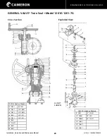
GENERAL VALVE
®
Twin Seal
™
Model 1500G
OPERATOR ASSEMBLY
1.
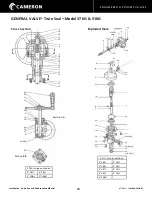
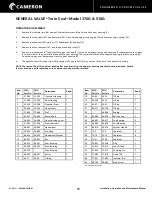
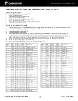
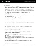
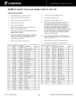
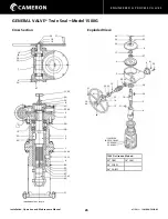
Install the two bearings (28) and bearing retainer at the top end of the upper stem (5).
NOTE: These are radial thrust bearings and must be installed such that the widest surfaces of the inner raceways are back to back.
INCORRECT INSTALLATION WILL RESULT IN SERIOUS DAMAGE.
2.
Apply a smooth even coating of Form-a-Gasket
®
to the bottom flange of the upper housing (2) and fasten to the lower housing (1)
with studs (32) and nuts (40).
3.
Apply a liberal coating of grease to all surfaces of the upper stem (5) and lower stem (4).
4.
Thread the two stems together such that the drive pin in the upper stem comes against the shoulder at the top of the lower stem
and the detent recess in the upper stem is exactly in line with the roller opening in the lower stem. This operation may require
several attempts as the threads are multiple start and do not always assemble correctly with the first try.
5.
Install the indicator shaft (12) up through both stems and secure
with
nut (43) in the bottom of the lower stem.
6.
Install O-Ring (23) in the lower housing.
7.
Place the roller (21) in the side opening of the lower stem (4). A liberal application of grease will hold it in place.
8.
Place the stems with bearings (28), bearing retainer and roller (21) assembled down through the top of the upper housing until
the lower of the two bearings rests on the shoulder in the upper housing.
9.
Apply a smooth even coating of Form-a-Gasket
®
to the surface of the guide pin boss on the lower housing.
10. Insert the guide pin (16) to fully engage the slot in the lower stem and fasten with cap screws (33).
11. Place the gear key (20) in the keyway of the upper stem.
12. Place the tapered roller bearing cones (29) on each end of the worm shaft (7) with the large diameter of the cone taper
against each shaft
shoulder.
13. Assemble the cups (30) on the cones.
14. Install the worm shaft in the gear housing.
15. Apply a smooth even coating of Form-a-Gasket
®
to motor adapter mounting surface of the gear housing.
16. Install O-Ring (22) in the bearing cap (10) and fasten to gear housing with screws (36). Be sure to re-install the plastic shims
between the gear housing and motor adapter.
17. Install worm gear (6) in gear housing with hub down (toward smaller opening).
18. Apply a smooth even coating of Form-a-Gasket
®
to the top flange of the upper housing.
19. Place the gear housing with assembled parts on top of the upper housing guiding the worm gear keyway over the key (20) in the
upper stem and fasten to the upper housing with capscrews (38).
20. Install ball bearing (27) over upper stem and secure with upper stem nut.
21. Install insert and set screw into upper stem nut.
22. Fill the gear housing with grease up to the top of the worm gear.
23. Apply a smooth even coating of Form-a-Gasket
®
around top surface of the gear housing.
24. Install the grease seal (26) in the gear housing cover (8). Slide the cover over the indicator shaft (12) and ball bearing (27) and
secure to the top of the gear housing with capscrews (35).
25. Install stem protector (24) and secure indicator flag (11) in place with set screw (39).

