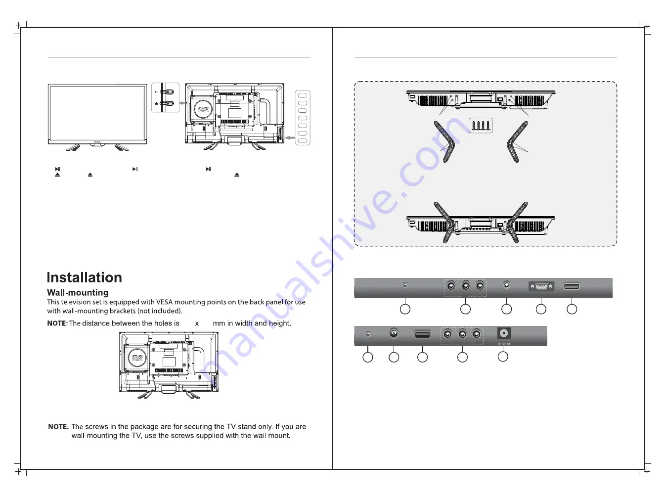
TV Controls
Controls on the TV
7
Base bracket installation
6
200 100
1. After you load a disc, press to play the disc, and press twice to pause.
2. Press the button when the power is on the disc will eject, Press the button again to load the
disc automatically.
3.
INPUT
- This button switches between all the different sources of the TV. When the OSD is active,
this button acts as the enter button and confirms the menu selection.
4.
MENU
- This button activates the OSD menu. If a sub-menu is active, pressing this button will return
the selection to the previous menu level.
5.
VOL(+)
- This button increases the TV’s volume. If the OSD menu is active, pressing this button will
move the selection to the right.
6.
VOL(-)
- This button decreases the TV’s volume. If the On Screen Display(OSD) menu is active,
pressing this button will move the selection to the left.
7.
CH(+)
- This button performs the channel up function. If the OSD menu is active, this button functions
as up control for the menu.
8.
CH(-)
- This button performs the channel down function. If the OSD menu is active, this button
functions as down control for the menu.
9.
STANDBY
- Turn on the TV by pressing the button once. Press the button again to turn off the TV.
1.
Earphone out:
Output for headphones or head units such as RV Media Head Units with TV input.
2.
AV Inputs:
Composite Video & Audio (A/V) in.
3.
PC Audio Input:
Connect to the audio output jack on a computer.
4.
VGA Input:
Connect to a computer’s VGA output jack.
5.
HDMI Input:
HDMI in.
6.
COAXIAL Out:
Digital Audio output for Surround Sound amplifiers and other devices.
7.
RF Input:
Connect to an external antenna to receive ATV/DTV TV signals
in ATV/DTV mode.
8.
USB
: USB/Multimedia input.
9
.
Y/Pb/Pr Input:
Component Video in.
10.
POWER:
(DC 12/24V) input
Rear Bottom
Rear Side
10
1
2
4
5
3
EARPHONE
OUT
VIDEO
R
L
VGA
HDMI
PC
AUDIO
IN
RF
IN
USB
8
COAXIAL
OUT
Y
Pr
Pb
7
9
6
IN
IN
TV Inputs & Outputs
INPUT
MENU
VOL+
VOL-
CH+
CH-
STANDBY
Instructions:
1. Place the TV on a flat and clean surface
2. Attach the 1st bracket with screws through holes B into A.
3. Attach the 2nd bracket with screws through holes D in to C.
Screws
Screw hole A
Screw hole B
Screw hole C
Screw hole D
DC 12V
For wall mounting, remove the 4 screws
and remove the two Base Brackets.


