


L
N
+ -
+
E
-
A
B
GND
EbA
EbA
EbI
EbI
10
S2
S1
2
EM
4
3
2
1
11
6
7
8
9
15
14
3
2
2
4
5
11
10
12
13
1
16
TOR100
L
N
+
E
-
10
2
1
11
1,6 A-F
TOR100B
17
9
7
6
4
3
8
10
6
17
PST004
p.
8
- M
an
u
al
:
F
A
0
0
6
1
3
-E
N
FA
0
0
6
1
3
-E
N
v.
1
1
- 1
1/
2
0
1
6 - © C
A
M
E S
.p.
A
. T
h
e d
ata a
n
d i
nf
or
m
ati
on i
n th
is
m
an
u
al
m
ay b
e c
h
an
g
ed at a
ny ti
m
e a
n
d w
ith
ou
t n
oti
ce
.
FUSE TABLE
TOR100A
TOR100B
Line fuses (A)
1.6 (230 V)
3.15 (120 V)
Accessories (A)
1.6
6.3
230 V AC power supply for transformer
(default connections)
120 V AC power supply for transformer
(Reverse cables
and
)
Ref.
Description
L1T = White
L2T = Red
Black (isolated)
Ref.
Description
L1T = White
Red (
*
isolated)
L2T = Black
Replace the 1.6 A line fuse with a 3.15 A unit.
⚠
*
Operations reserved for the installing technician!
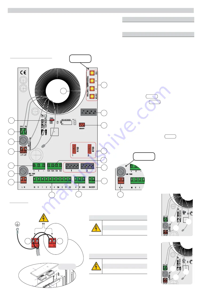
ELECTRICAL CONNECTIONS
Description of the components
⚠
Remove line voltage before intervening on the control board.
Control board power supply (V - 50/60 Hz): 120 - 230 AC.
Control device power supply: 24 V AC.
⚠
The total power of the accessories should not exceed 35 W.
The output power at 24V AC is SELV type for which there is a risk of electric shock.
All the connections are protected by quick fuses.
Power supply
120 - 230 V AC (50 / 60 Hz)
1. Transformer
2. Transformer terminal block
3. Accessory
fuse
4. Entrance/exit sensor terminal block
5. Line
fuse
6. Power supply terminal block
7. Control and safety device terminal block
8. Electric lock terminal block
9. Buzzer terminal block
PST003
PST003
10. Transponder connectors
PST001
PST001
11. R700 card connectors
12. Memory Roll card connector
13. Direction arrows with display terminal block
14. Function programming buttons
15. RBM84 terminal block
16. Indicator LEDS
17. Arm drop power supply terminal block
PST004
PST004