background image

p. 

22

 - M

an

u

al

 c

od

e: 

F

A

0

1

0

3

0

-E

N

FA

0

1

0

3

0

-E

N

 v.


11

- 0

1/

2

0

18 - © C

am

e S

.p.

A

. - T

h

e m

an

u

al

's c

onte

nts m

ay b

e e

d

ite

d at a

ny ti

m

e w

ith

ou

t n

oti

ce

.

Danger of hand crushing

Danger! High voltage.

No transiting while the barrier is moving

WARNING!

Important safety instructions.

READ CAREFULLY

P

REMISE

• T

HIS


PRODUCT


SHOULD


ONLY


BE


USED


FOR


THE


PURPOSE


FOR


WHICH


IT


WAS


EXPLICITLY


DESIGNED

. A

NY


OTHER


USE


IS


DANGEROUS

. C

AME

 S.

P

.A. 

IS


NOT


LIABLE


FOR


ANY


DAMAGE


CAUSED


BY


IMPROPER

ERRONEOUS


OR


UNREASONABLE


USE

. • 

P

RODUCT


SAFETY


AND


CORRECT


INSTALLATION


ARE


SUBJECT


TO


RESPECTING


THE


PRODUCT

'

S


TECHNICAL


CHARACTERISTICS


AND


THE


CORRECT


INSTALLATION


PROCE

-

DURE


IN


LINE


WITH


PROFESSIONAL


STANDARDS

SAFETY


REGULATIONS


AND


USAGE


SPECIFICATIONS


AS


SET


OUT


IN


THE


TECHNICAL


DOCUMENTATION


THAT


COMES


WITH


THE


PRODUCT

. • K

EEP


THESE


PRECAUTIONS


TOGETHER


WITH


THE


INSTALLATION


AND


USAGE


MANUALS


THAT


COME


WITH


THE


OPERATOR


SYSTEM

.

B

EFORE


INSTALLING

(C

HECK


THE


CONTENTS

IF


SOMETHING


IS


MISSING

DO


NOT


CONTINUE


UNTIL


YOU


HAVE


COMPLIED


WITH


ALL


SAFETY


PROVISIONS

)

• F

ITTING


AND


TESTING


MUST


ONLY


BE


PERFORMED


BY


QUALIFIED


TECHNICIANS


• L

AY


THE


CABLES

INSTALL


AND


CONNECT


UP


THE


PRODUCT

AND


RUN


TEST

-

ING


FOLLOWING


PROFESSIONAL


PROCEDURES


IN


COMPLIANCE


WITH


THE


STANDARDS


AND


REGULATIONS


IN


FORCE

 • B

EFORE


BEGINNING


ANY


OPERATION

READ


ALL


INSTRUCTIONS


CAREFULLY

INCORRECT


INSTALLATION


MAY


CAUSE


SERIOUS


HARM


TO


PEOPLE


OR


PROPERTY

 • M

AKE


SURE


THE


BOOM


IS


IN


GOOD


MECHANICAL


ORDER

BALANCED


AND


ALIGNED

AND


THAT


IT


OPENS


AND


CLOSES


PROPERLY

. I

F


REQUIRED

FIT


SUITABLE


PROTECTIVE


DEVICES


OR


USE


SUITABLE


ADDITIONAL


SAFETY


SENSORS


• I

F


THE


OPERATOR


IS


TO


BE


INSTALLED


AT


A


HEIGHT


OF


OVER

 2.5 

M


FROM


THE


GROUND


OR


OTHER


ACCESS


LEVEL

MAKE


SURE


YOU


HAVE


ANY


NECESSARY


PROTEC

-

TIVE


DEVICES


OR


WARNINGS


IN


PLACE

 • M

AKE


SURE


THAT


THE


OPENING


AUTOMATIC


BARRIER


DOES


NOT


CREATE


A


HAZARD

 • D

O


NOT


INSTALL


THE


OPERATOR


UPSIDE


DOWN


OR


ON


ELEMENTS


THAT


COULD


BEND

. I

F


NECESSARY

ADD


SUITABLE


REIN

-

FORCEMENTS


TO


THE


ANCHORING


POINTS

 • M

AKE


SURE


THE


TEMPERATURE


RANGE


SHOWN


ON


THE


OPERATOR


IS


SUITABLE


FOR


THE


INSTALLATION


SITE

 • D

O


NOT


INSTALL


ON


SLOPING


OR


UNEVEN


SURFACES

 • M

AKE


SURE


ANY


SPRINKLER


SYSTEMS


CANNOT


WET


THE


OPERATOR


FROM


THE


GROUND


UP

.

I

NSTALLATION

• S

UITABLY


SECTION


OFF


AND


DEMARCATE


THE


ENTIRE


INSTALLATION


SITE


TO


PRE

-

VENT


UNAUTHORISED


PERSONS


FROM


ENTERING


THE


AREA

ESPECIALLY


MINORS


AND


CHILDREN

 • B

E


CAREFUL


WHEN


HANDLING


OPERATORS


THAT


WEIGH


OVER

 20 

KG

I

F


NEED


BE

USE


PROPER


SAFETY


HOISTING


EQUIPMENT

 • T

HE

 CE-

MARKED


SAFETY


DEVICES

 (

PHOTOCELLS

STEPPING


PLATES

SAFETY


EDGES

EMERGENCY


BUTTONS

ETC

.) 

MUST


BE


FITTED


IN


COMPLIANCE


WITH


PROFESSIONAL


STANDARDS


AND


THE


REGULATIONS


IN


FORCE

TAKING


INTO


ACCOUNT


THE


ENVIRONMENT

TYPE


OF


SER

-

VICE


REQUIRED


AND


THE


WORKING


FORCES


APPLIED


TO


THE


MOVING


BARRIERS

A

NY


POINTS


AT


WHICH


THERE


IS


A


RISK


OF


CRUSHING

SHEARING


OR


CONVEYING


MUST


BE


SENSOR

-

PROTECTED

 • A

NY


RESIDUAL


RISKS


MUST


BE


CLEARLY


SHOWN

 • 

A

LL


OPENING


CONTROLS

 (

BUTTONS

KEY

-

SWITCH


SELECTORS

MAGNETIC


READERS

ETC

.) 

MUST


BE


INSTALLED


AT


LEAST

 1.85 

M


FROM


THE


PERIMETER


OF


THE


BAR

-

RIER

'

S


WORKING


AREA

OR


WHERE


THEY


CANNOT


BE


REACHED


FROM


THE


OUTSIDE


THROUGH


THE


BARRIER

. A

NY


DIRECT


CONTROLS

 (

BUTTONS

TOUCH


PANELS

ETC

.) 

MUST


BE


INSTALLED


AT


LEAST

 1.5 

M


FROM


THE


GROUND


AND


MUST


NOT


BE


ACCES

-

SIBLE


TO


UNAUTHORISED


PERSONS

 • T

HE


AUTOMATIC


BARRIER


MUST


BEAR


VISIBLE


IDENTIFICATION


DATA

. • B

EFORE


CONNECTING


THE


BARRIER


TO


THE


POWER


SUPPLY

MAKE


SURE


THAT


THE


IDENTIFICATION


DATA


CORRESPOND


TO


THE


MAINS


DATA

 • T

HE


AUTOMATIC


BARRIER


MUST


BE


CONNECTED


TO


AN


EFFECTIVE


EARTHING


SYSTEM


THAT


COMPLIES


WITH


LEGAL


STANDARDS

.

• T

HE


MANUFACTURER


DECLINES


ALL


LIABILITY


FOR


USE


OF


NON

-

ORIGINAL


PROD

-

UCTS

WHICH


WOULD


ALSO


RESULT


IN


WARRANTY


LOSS

 • A

LL


HOLD

-

TO

-

RUN


CON

-

TROLS


MUST


BE


FITTED


IN


PLACES


FROM


WHICH


THE


MOVING


BARRIER


AND


TRANSIT

/

MANOEUVRING


AREAS


ARE


VISIBLE

 • W

HERE


MISSING

APPLY


A


PERMANENT


SIGN


SHOWING


THE


POSITION


OF


THE


RELEASE


DEVICE

 • B

EFORE


DELIVERING


THE


PROD

-

UCT


TO


THE


USER

MAKE


SURE


THE


SYSTEM


IS


COMPLIANT


WITH


STANDARDS

 EN 

12453 

AND

 EN 12445 (

REGARDING


IMPACT


FORCES

), 

AND


ALSO


MAKE


SURE


THE


SYSTEM


HAS


BEEN


PROPERLY


ADJUSTED


AND


THAT


ANY


SAFETY

PROTECTION


AND


MANUAL


RELEASE


DEVICES


ARE


WORKING


PROPERLY

 • A

PPLY


WARNING


SIGNS


WHERE


NECESSARY


AND


IN


A


VISIBLE


PLACE

 (

E

.

G

A


PANEL


ON


THE


BARRIER

).

U

SER


INSTRUCTIONS


AND


RECOMMENDATIONS

• K

EEP


BARRIER


OPERATION


AREAS


CLEAN


AND


FREE


OF


ANY


OBSTRUCTIONS

M

AKE


SURE


THE


OPERATING


FIELD


OF


THE


PHOTOCELLS


IS


CLEAR


OF


ANY


OB

-

STRUCTIONS

 • D

O


NOT


ALLOW


CHILDREN


TO


PLAY


WITH


FIXED


COMMANDS

OR


TO


LOITER


IN


THE


BARRIER


MANOEUVRING


AREA

. K

EEP


ANY


REMOTE


CONTROL


DEVICES

 (

TRANSMITTERS

OR


ANY


OTHER


COMMAND


DEVICE


OUT


OF


THE


REACH


OF


CHILDREN

TO


PREVENT


THE


OPERATOR


FROM


BEING


ACCIDENTALLY


ACTIVATED

 • 

T

HE


APPARATUS


MAY


BE


USED


BY


CHILDREN


OF


EIGHT


YEARS


AND


ABOVE


AND


BY


PEOPLE


WITH


PHYSICAL


OR


COGNITIVE


DISABILITIES

OR


THOSE


LACKING


EXPERIENCE


OR


RELEVANT


KNOWLEDGE

PROVIDED


THEY


ARE


CLOSELY


SUPERVISED


OR


ONCE


THEY


HAVE


BEEN


PROPERLY


INSTRUCTED


ON


HOW


TO


USE


THE


APPARATUS


SAFELY


AND


ON


THE


POTENTIAL


HAZARDS


INVOLVED

. C

HILDREN


MUST


NOT


PLAY


WITH


THE


APPARATUS

. U

SER


CLEANING


AND


MAINTENANCE


MUST


NOT


BE


PERFORMED


BY


UN

-

SUPERVISED


CHILDREN

 • F

REQUENTLY


CHECK


THE


SYSTEM


FOR


ANY


MALFUNCTIONS


OR


SIGNS


OF


WEAR


AND


TEAR


OR


DAMAGE


TO


THE


MOVING


STRUCTURES

OPERATOR


COMPONENTS

ANCHORING


POINTS


AND


DEVICES

CABLES


AND


ACCESSIBLE


CON

-

NECTIONS

. K

EEP


ANY


JOINTS

 (

HINGES

AND


FRICTION


POINTS

 (

BOOM


FLANGE

CLEAN


AND


LUBRICATED

 • P

ERFORM


FUNCTIONAL


CHECKS


ON


THE


PHOTOCELLS


EVERY


SIX


MONTHS

. A

LWAYS


MAKE


SURE


THE


PHOTOCELL


GLASS


COVERS


ARE


CLEAN

 (

USE


A


DAMP


CLOTH

DO


NOT


USE


SOLVENTS


OR


CHEMICALS


THAT


COULD


DAMAGE


THE


DEVICES

) • I

F


REPAIRS


OR


MODIFICATIONS


ARE


REQUIRED


TO


THE


SYSTEM

RELEASE


THE


OPERATOR


AND


DO


NOT


USE


IT


UNTIL


THE


SAFETY


CONDITIONS


HAVE


BEEN


RESTORED

 • C

UT


OFF


THE


ELECTRICAL


POWER


SUPPLY


BEFORE


RELEASING


THE


OP

-

ERATOR


FOR


MANUAL


OPENINGS

. R

EAD


THE


INSTRUCTIONS

 • I

F


THE


POWER


SUPPLY


CABLE


IS


DAMAGED

IT


MUST


BE


REPLACED


BY


THE


MANUFACTURER


OR


ITS


AUTHOR

-

ISED


TECHNICAL


ASSISTANCE


SERVICE


OR

IN


ANY


CASE

BY


SIMILARLY


QUALIFIED


PERSONS

TO


PREVENT


ANY


RISK

 • U

SERS


MUST


NOT


PERFORM


ANY


OPERATIONS


THAT


ARE


NOT


EXPRESSLY


REQUIRED


OF


THEM


AND


WHICH


ARE


NOT


LISTED


IN


THE


MANUALS

. F

OR


ANY


REPAIRS

MODIFICATIONS

ADJUSTMENTS


AND


NON

-

SCHEDULED


MAINTENANCE

PLEASE


CONTACT


THE


TECHNICAL


ASSISTANCE


SERVICE

 • L

OG


THE


WORK


IN


THE


PERIODIC


MAINTENANCE


LOG

.

A

DDITIONAL


GENERAL


RECOMMENDATIONS

• K

EEP


AWAY


FROM


AND


DO


NOT


LOITER


NEAR


THE


BARRIER


BOOM


OR


MOVING


MECHANICAL


PARTS

 • D

O


NOT


ENTER


THE


AREA


OF


OPERATION


WHEN


THE


BARRIER


IS


MOVING

 • D

O


NOT


COUNTER


OR


OBSTRUCT


THE


OPERATOR

'

S


MOVEMENT


AS


THIS


COULD


CAUSE


DANGER

 • A

LWAYS


PAY


SPECIAL


ATTENTION


TO


ANY


DANGEROUS


POINTS

WHICH


MUST


BE


LABELLED


WITH


SPECIFIC


PICTOGRAMS


AND

/

OR


BLACK


AND


YELLOW


STRIPES

 • W

HEN


USING


A


SELECTOR


SWITCH


OR


A


HOLD

-

TO

-

RUN


CONTROL

KEEP


CHECKING


THAT


THERE


ARE


NO


PERSONS


WITHIN


THE


OPERATING


RANGE


OF


ANY


MOVING


PARTS

UNTIL


THE


CONTROL


IS


RELEASED

 • T

HE


BARRIER


MAY


MOVE


AT


ANY


TIME


AND


WITHOUT


WARNING

 • A

LWAYS


CUT


OFF


THE


POWER


SUPPLY


BEFORE


PERFORMING


ANY


MAINTENANCE


OR


CLEANING

.


Summary of Contents for G2080E

Page 1: ...IT Italiano EN English FR Fran ais RU FA01030M04 Barriere automatiche serie GARD 8 G2080E G2080IE MANUALE DI INSTALLAZIONE...

Page 2: ...DEVE ESSERE COLLEGATA AD UN EFFICACE IMPIANTO DI MESSA A TERRA REALIZZATO A NORMA IL PRODUTTORE DECLINA OGNI RESPONSABILIT PER L IMPIEGO DI PRODOTTI NON ORIGINALI QUESTO IMPLICA INOLTRE LA DECADENZA...

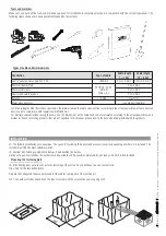
Page 3: ...sposizione per accessori Destinazione d uso La barriera automatica stata progettata per l utilizzo in parcheggi privati o pubblici Ogni installazione e uso difformi da quanto indicato nel seguente man...

Page 4: ...ne delle parti 1 Cupola 2 Piastra albero motore 3 Piastra intermedia 4 Copri attacco asta 5 Copertura di protezione anticesoiamento 6 Armadio 7 Supporto per selettori a chiave e digitali 8 Quadro coma...

Page 5: ...ve vigenti Importante L uso di dispositivi di comando di sicurezza e di accessori originali CAME garantisce una facile installazione e manutenzione dell impianto Verifiche preliminari Prima di procede...

Page 6: ...ggio solido e stabile dell armadio preparare una piazzola di cemento Fare lo scavo per la cassa matta Preparare i tubi corrugati necessari per i collegamenti provenienti dal pozzetto di derivazione Il...

Page 7: ...cassa matta per armare il cemento Assemblare le quattro zanche di ancoraggio alla piastra di fissaggio Posizionare la piastra sopra la griglia Riempire la cassa matta di cemento la base deve essere pe...

Page 8: ...e modo allentare il grano del braccio motore togliere la staffa attacco molle e la biella di trasmissione dal braccio leva ruotare il braccio leva di 90 fissare la staffa attacco molle e la biella di...

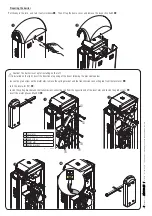
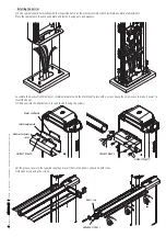
Page 9: ...sta con le viti Piastra albero motore Piastra intermedia Copri attacco asta Tappo per asta Installazione della barriera consigliabile installare l armadio con lo sportello di ispezione dal lato pi pra...

Page 10: ...2 2 5 2 5 3 3 3 5 3 5 4 4 4 5 4 5 5 5 5 5 5 5 6 6 6 5 6 5 7 7 7 6 Asta A A A A A B A B A B B B B B B C C C Asta con appoggio mobile 001G02808 A A A A A A A B A B B B B B B C C C Asta con cordone lumin...

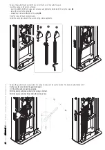
Page 11: ...funzionamento della molla Con asta posizionata in verticale la molla non in tensione Con asta posizionata in orizzontale la molla in tensione Sbloccare il motoriduttore e posizionare l asta in vertica...

Page 12: ...re per scheda AF 14 Morsettiera per antenna 15 Morsettiera per dispositivi di comando e sicurezza 16 Morsettiera per collegamento in abbinato bussola CRP 17 Morsettiera per selettore a tastiera 18 Mor...

Page 13: ...i accessori a 24 V AC normalmente a 24 V DC quando intervengono le batterie d emergenza Potenza complessiva consentita 40 W Trasformatore Rosso Bianco Blu Arancione Motoriduttore 24 V DC con encoder I...

Page 14: ...la funzione F 1 Funzione APRE CHIUDE INVERSIONE passo passo da dispositivo di comando contatto NO Selettore a tastiera Transponder o lettore tessere Inserire la scheda di decodifica R700 per far ricon...

Page 15: ...mmediata con attesa ostacolo in chiusura Chiusura dell asta dopo il passaggio di un veicolo nel raggio di azione dei dispositivi di sicurezza Durante la fase di chiusura i dispositivi eseguono anche l...

Page 16: ...nuale sono da ritenersi suscettibili di modifica in qualsiasi momento senza obbligo di preavviso Sleep Mode La funzione Sleep Mode consente la riduzione del consumo energetico delle fotocellule in sta...

Page 17: ...Determinazione dei punti di finecorsa Chiudere lo sportello d ispezione e dare tensione all impianto Azionare la barriera per verificare che l asta sia parallela al piano stradale in posizione di chiu...

Page 18: ...nu spostarsi con le frecce Per aumentare o diminuire il valore usare le frecce per uscire dal menu attendere 10 secondi o premere ESC poi premere ENTER per confermare Navigazione menu poi premere ENTE...

Page 19: ...seriale F 50 Salvataggio dati nella memory roll F 51 Lettura dati dalla memory roll F 52 Passaggio parametri da Master a Slav F 60 Funzione Sleep Mode F 61 Funzione prelampeggio U 1 Tipo di comando da...

Page 20: ...ccesa dal momento in cui la barriera inizia l apertura no alla completa chiusura compreso il tempo di chiusura automatica Nel caso non venga inserita la chiusura automatica rimane accesa solo durante...

Page 21: ...ntamento F37 Punto rallentamento apertura 40 40 della corsa 60 60 della corsa Regolazione in percentuale sulla corsa totale dell asta del punto di inizio del rallentamento in apertura Attenzione La pe...

Page 22: ...parametri di velocit rallentamento e taratura Questo per garantire il corretto funzionamento dell automazione A 2 Test motore 0 Disattivata 1 Attivata Per verificare il corretto senso di rotazione del...

Page 23: ...e l operazione di taratura automatica della corsa Taratura corsa Prima di effettuare la taratura della corsa de nire il tipo di asta veri care che l asta sia bilanciata e controllare che l area di man...

Page 24: ...ENTER per confermare 2 Selezionare un comando da associare all utente I comandi sono passo passo apre chiude 1 apre 3 apertura parziale pedonale 4 Il comando di apertura parziale pedonale appare solo...

Page 25: ...ti e alla configurazione dell impianto per poi riutilizzarli con un altra scheda elettronica anche in un altro impianto SBLOCCO DELL ASTA L operazione deve essere effettuata in assenza di tensione Ins...

Page 26: ...tomatica sul quadro dell automazione SLAVE Memorizzazione Eseguire la procedura di inserimento utente con comando SOLO APRE e APERTURA PARZIALE PEDONALE sul quadro MASTER Con gurazione dell automazion...

Page 27: ...e SLAVE Importante Attivare la funzione F 19 tempo chiusura automatica sul quadro di entrambe le automazioni Memorizzazione Eseguire la procedura di inserimento utente con comando SOLO APRE e PASSO PA...

Page 28: ...e i fusibili La barriera non effettua la chiusura automatica 11 12 13 4 I contatti NC sono aperti La barriera non funziona con il trasmettitore 2 14 16 6 Disattivare la funzione MASTER SLAVE L asta i...

Page 29: ...i momento senza obbligo di preavviso Manutenzione periodica Prima di qualsiasi operazione di manutenzione togliere la tensione per evitare possibili situazioni di pericolo causate da accidentali movim...

Page 30: ...____________________________________________________ Timbro installatore Nome operatore Data intervento Firma tecnico Firma committente Intervento effettuato __________________________________________...

Page 31: ...maltiti senza alcuna difficolt semplicemente effettuando la raccolta differenziata per il riciclaggio Prima di procedere sempre opportuno verificare le normative specifiche vigenti nel luogo d install...

Page 32: ...t 15 31030 Dosson di Casier Treviso Italy tel 39 0422 4940 fax 39 0422 4941 Manuale FA01030 IT ver 1 01 2018 CAME S p A I contenuti del manuale sono da ritenersi suscettibili di modifica in qualsiasi...

Page 33: ...Automatic barriers GARD 8 series G2080E G2080IE INSTALLATION AND OPERATION English FA01030 EN...

Page 34: ...ORRESPOND TO THE MAINS DATA THE AUTOMATIC BARRIER MUST BE CONNECTED TO AN EFFECTIVE EARTHING SYSTEM THAT COMPLIES WITH LEGAL STANDARDS THE MANUFACTURER DECLINES ALL LIABILITY FOR USE OF NON ORIGINAL P...

Page 35: ...finish steel set up to fit accessories Intended use The automatic barrier is designed to be used in public and private parking facilities Any installation and use other than that specified in this man...

Page 36: ...tion of parts 1 Dome cover 2 Motor shaft plate 3 Intermediate plate 4 Boom attachment cover 5 Anti shearing protective cover 6 Cabinet 7 Casing for key switch and digital selectors 8 Control panel 9 L...

Page 37: ...iance with the regulations in force Important Using original CAME control and safety devices and accessories ensures easy installation and system maintenance Preliminary checks Before installation mak...

Page 38: ...will have to use a cement slab Dig a hole for the foundation frame Prepare the corrugated tubes you will need for the cables coming out of the junction pit The number of tubes depends on the type of...

Page 39: ...reinforce the concrete Attach the four anchoring clamps to the anchoring plate Place the plate over the iron cage Fill the foundation frame with concrete The base must be perfectly level and the bolts...

Page 40: ...the grub screw on the motor arm remove the spring bracket and the transmission connecting rod from the lever arm turn the lever arm 90 fasten the spring bracket and the transmission connecting rod fr...

Page 41: ...Motor shaft plate Intermediate plate Boom attachment cover Boom cap Installing the barrier The cabinet should be installed with the inspection hatch on the most accessible side to facilitate any work...

Page 42: ...2 to 2 5 2 5 to 3 3 to 3 5 3 5 to 4 4 to 4 5 4 5 to 5 5 to 5 5 5 5 to 6 6 to 6 5 6 5 to 7 7 to 7 6 Boom A A A A A B A B A B B B B B B C C C Boom with 001G02808 swing post A A A A A A A B A B B B B B...

Page 43: ...properly With the boom positioned vertically the spring is not taut With the boom positioned horizontally the spring is taut Release the gearmotor and position the boom vertically Lock the gearmotor...

Page 44: ...card connector 14 Terminal board for antenna 15 Terminal board for control and safety devices 16 Terminal board for paired alternate CRP connection 17 Terminal board for keypad selector 18 Terminal b...

Page 45: ...wering up accessories 24 V AC normally 24 V DC when the emergency batteries are operating Overall allowed power 40 W Transformer Red White Blue Orange 24 V DC gearmotor with encoder The gearmotor is a...

Page 46: ...ct 0 Disabled from the function F 1 OPEN CLOSE INVERT step by step function from control device N O contact Keypad selector Transponder or card reader Insert the decoding card R700 for the TSP00 senso...

Page 47: ...closure with obstacle stand by during closing Closing the boom after a vehicle has passed through the operating area of the safety devices During closing the devices also run functionC4 obstacle stand...

Page 48: ...30 EN FA01030 EN v 1 1 01 2018 Came S p A The manual s contents may be edited at any time without notice Sleep mode The Sleep mode function reduces the energy consumption of the photocells in stand by...

Page 49: ...sing a counter nut Establishing the limit switch points Close the inspection hatch and power the system Activate the barrier to check whether the boom is parallel to the road surface when closed and a...

Page 50: ...ow keys for the submenus To increase or decrease a value use the arrow keys to exit the menu wait 10 seconds or press ESC then press ENTER to confirm Menu navigation then press ENTER The ESC key is fo...

Page 51: ...on F 50 Save data to the memory roll F 51 Read data on the memory roll F 52 Parameter transfer from Master to Slave F 60 Sleep mode F 61 Pre flashing function U 1 Type of command to associate with use...

Page 52: ...stays on from the moment the barrier begins to open until it is fully closed including automatic closing time Where the automatic closing function is not activated it only stays on during barrier mov...

Page 53: ...g slow down for the boom as a percentage of the total travel Warning The percentage varies depending on the type of boom for booms with a joint between 2 m and 4 m set the percentage from 40 to 60 for...

Page 54: ...eed slow down and calibration parameters This is so as to ensure that the operator functions correctly A 2 Motor test 0 Deactivated 1 Activated To check that the gearmotors rotate in the right directi...

Page 55: ...ENTER to confirm the automatic travel calibration Travel calibration Before calibrating the travel identify the type of boom check that the boom is balanced and check that the manoeuvring area is cle...

Page 56: ...ect a command to associate with the user The commands are step by step open close 1 open 3 partial pedestrian opening 4 The partial pedestrian command only appears if function F 49 is active Press ENT...

Page 57: ...r and system configuration data so that they can be reused with another electronic circuit board including in another system RELEASING THE BOOM This procedure must be done with the mains power cut off...

Page 58: ...he SLAVE operator Saving Follow the procedure for entering a user with the OPEN and PARTIAL PEDESTRIAN OPENING command on the MASTER panel Configuring the MASTER operator Select function F 49 Press EN...

Page 59: ...nel of the SLAVE operator only Important Activate the F 19 function automatic closing time on the panel on both operators Saving Follow the procedure for entering a user with the OPEN and STEP BY STEP...

Page 60: ...wer supply and fuses The barrier does not close automatically 11 12 13 4 The N C contacts are open The barrier does not work with the transmitter 2 14 16 6 Deactivate the MASTER SLAVE function The boo...

Page 61: ...dited at any time without notice Periodic maintenance Before carrying out any maintenance disconnect the power supply to prevent any hazardous situations caused by the boom moving accidentally Periodi...

Page 62: ..._____ Fitter s stamp Name of operator Job performed on date Technician s signature Requester s signature Job performed _________________________________________________________________________________...

Page 63: ...simply separated from other waste for recycling Always make sure you comply with local laws before dismantling and disposing of the product DISPOSE OF THE PRODUCT RESPONSIBLY DISPOSING OF THE PRODUCT...

Page 64: ...rtiri Della Libert 15 31030 Dosson di Casier Treviso Italy tel 39 0422 4940 fax 39 0422 4941 Manual code FA01030 EN ver 1 01 2018 CAME S p A The contents of this manual may be changed at any time with...

Page 65: ...Barri res automatiques s rie GARD 8 G2080E G2080IE MANUEL D INSTALLATION Fran ais FA01030 FR...

Page 66: ...CACE ET CONFORME AUX NORMES EN VIGUEUR LE PRODUCTEUR D CLINE TOUTE RESPONSABILIT EN CAS D UTILISATION DE PRODUITS NON ORIGINAUX CE QUI IMPLIQUE EN OUTRE L ANNULATION DE LA GARANTIE TOUTES LES COMMANDE...

Page 67: ...s Utilisation pr vue La barri re automatique a t con ue pour une utilisation dans des parkings priv s ou publics Toute installation et toute utilisation autres que celles qui sont indiqu es dans ce ma...

Page 68: ...s 1 Couvercle 2 Plaque arbre moteur 3 Plaque interm diaire 4 Cache plaque de fixation de la lisse 5 Carter de protection anti cisaillement 6 F t 7 Support pour s lecteurs cl et num riques 8 Armoire de...

Page 69: ...ormes en vigueur Important L utilisation de dispositifs de commande de s curit et d accessoires CAME garantit la simplicit du montage et de l entretien de l installation Contr les pr liminaires Avant...

Page 70: ...rmet pas une fixation solide et stable de l armoire pr parer un bloc de ciment Creuser la fosse pour le coffrage Pr parer les gaines annel es pour les raccordements issus du bo tier de d rivation Le n...

Page 71: ...r couler le ciment Assembler les 4 agrafes de fixation la plaque Positionner la plaque sur la grille Remplir le coffrage de ciment la plaque doit tre parfaitement nivel e et avec le filetage des vis t...

Page 72: ...eur enlever l trier de fixation des ressorts ainsi que la bielle de transmission du bras du levier tourner le bras du levier de 90 fixer l trier de fixation des ressorts ainsi que la bielle de transmi...

Page 73: ...r Plaque interm diaire Cache plaque de fixation de la lisse Couvercle pour lisse Installation de la barri re Il convient d installer l armoire avec la porte de visite du c t le plus pratique pour les...

Page 74: ...55 mm DIMENSIONS DE LA LISSE m de 2 2 5 de 2 5 3 de 3 3 5 de 3 5 4 de 4 4 5 de 4 5 5 de 5 5 5 de 5 5 6 de 6 6 5 de 6 5 7 de 7 7 6 Lisse A A A A A B A B A B B B B B B C C C Lisse avec appui mobile 001G...

Page 75: ...Avec lisse positionn e dans le sens vertical le ressort n est pas tendu Avec lisse positionn e dans le sens horizontal le ressort est tendu D bloquer le motor ducteur et positionner la lisse dans le...

Page 76: ...teur pour carte AF 14 Bornier pour antenne 15 Bornier pour dispositifs de commande et de s curit 16 Bornier pour connexion vis vis SAS CRP 17 Bornier pour clavier code 18 Bornier pour dispositifs tran...

Page 77: ...des accessoires 24 VCA sur secteur 24 V CC durant l intervention des batteries de secours Puissance totale admise 40 W Transformateur Rouge Blanc Bleu Orange Motor ducteur 24 V CC avec encodeur Le mo...

Page 78: ...puis la fonction F 1 Fonction OUVERTURE FERMETURE INVERSION pas pas depuis un dispositif de commande contact NO S lecteur clavier Transpondeur ou lecteur de cartes Ins rer la carte de codage R700 pour...

Page 79: ...le en phase de fermeture fermeture de la lisse apr s le passage d un v hicule dans le rayon d action des dispositifs de s curit Durant la phase de fermeture les dispositifs ex cutent galement la fonct...

Page 80: ...ubir des modifications tout moment et sans aucun pr avis Mode Sommeil La fonction Mode Sommeil permet de r duire la consommation d nergie des photocellules en standby S lectionner 1 au moyen de la fon...

Page 81: ...ints de fin de course Fermer la porte de visite et mettre l installation sous tension Actionner la barri re pour s assurer que la lisse est bien parall le la surface de la route en position de fermetu...

Page 82: ...er dans les sous menus Se servir des fl ches pour augmenter ou diminuer la valeur pour sortir du menu attendre 10 secondes ou appuyer sur ESC puis appuyer sur ENTER pour confir mer Navigation menu pui...

Page 83: ...51 Lecture donn es de la m moire F 52 Passage param tres de Ma tre Esclave F 60 Fonction Mode Veille F 61 Fonction pr clignotement U 1 Type de commande associer l utilisateur au moyen d une commande r...

Page 84: ...ut de l ouverture de la barri re jusqu la fermeture totale y compris le temps de fermeture automatique d faut d activation de la fermeture automatique elle ne reste allum e que durant le mouvement La...

Page 85: ...tissement F37 Point ralentissement ouverture 40 40 de la course 60 60 de la course R glage en pourcentage sur la course totale de la lisse du point de d but du ralentissement en phase d ouverture Atte...

Page 86: ...ralentissement et r glage Il est ainsi possible de garantir le bon fonctionnement de l automatisme A 2 Test moteur 0 D sactiv e 1 Activ e Pour contr ler le bon sens de rotation de la lisse voir paragr...

Page 87: ...rmer l op ration de r glage automatique de la course Auto apprentissage course Avant de r gler la course d nir le type de lisse s assurer que la lisse est bien quilibr e et que la zone de man uvre ne...

Page 88: ...une commande associer l utilisateur Les commandes sont pas pas ouverture fermeture 1 ouverture 3 ouverture partielle pi tonni re 4 La commande d ouverture partielle pi tonne n appara t que si la fonc...

Page 89: ...nfiguration de l installation de mani re ce qu elles soient r utilisables sur une autre carte lectronique voire une autre installation D BLOCAGE DE LA LISSE Mettre hors tension avant d effectuer cette...

Page 90: ...orisation Ex cuter la proc dure d insertion utilisateur avec la commande OUVERTURE UNIQUEMENT et OUVERTURE PARTIELLE PI TONNE sur l armoire MA TRE Con guration de l automatisme MA TRE S lectionner la...

Page 91: ...ermeture automatique sur l armoire des deux automatismes M morisation Ex cuter la proc dure d insertion utilisateur avec la commande OUVERTURE UNIQUEMENT et PAS PAS sur l armoire MA TRE et la fonction...

Page 92: ...s La barri re n effectue pas la fermeture automatique 11 12 13 4 Les contacts NF sont ouverts La barri re ne fonctionne pas avec l metteur 2 14 16 6 D sactiver la fonction MA TRE ESCLAVE La lisse inve...

Page 93: ...t et sans aucun pr avis Entretien p riodique Avant toute autre op ration d entretien il est conseill de mettre hors tension pour viter toute situation de danger provoqu e par des d placements accident...

Page 94: ...___________________________ Timbre installateur Nom op rateur Date intervention Signature technicien Signature client Intervention effectu e ___________________________________________________________...

Page 95: ...lt en proc dant tout simplement la collecte diff renci e pour le recyclage Avant d effectuer ces op rations il est toujours recommand de v rifier les normes sp cifiques en vigueur sur le lieu d instal...

Page 96: ...a Libert 15 31030 Dosson di Casier Treviso Italy tel 39 0422 4940 fax 39 0422 4941 Manuel FA01030 FR ver 1 01 2018 CAME S p A Le contenu de ce manuel est susceptible de subir des modifications tout mo...

Page 97: ...GARD 8 G2080E G2080IE FA01030 RU...

Page 98: ...2 FA01030 RU 1 01 2018 CAME S p A CAME S P A 2 5 20 1 8 1 5 EN12453 EN12445 8...

Page 99: ...1335 243 493 405 1305 max 7600 914 3 FA01030 RU 1 01 2018 CAME S p A AISI 304 G2080E G2080IE 7 60 G2080E G2080IE IP 54 50 60 230 24 15 300 600 90 4 8 C 20 55 i 1 202 I 91...

Page 100: ...3 2 4 5 6 1 9 10 11 12 8 13 15 14 7 16 7 16 7 SEL SET 4 FA01030 RU 1 01 2018 CAME S p A 1 2 3 4 5 6 7 8 9 10 11 12 13 14 15 16 SEL...

Page 101: ...CAME CAME 11 14 13 3 4 2 8 6 5 7 1 10 12 9 5 FA01030 RU 1 01 2018 CAME S p A 1 2 3 4 5 6 7 8 9 10 11 12 13 14 CAME 3 III...

Page 102: ...6 9 0 3 6 0 450 2 4 0 4 6 0 6 FA01030 RU 1 01 2018 CAME S p A 1 15 15 30 230 H05RN F 3G x 1 5 2 3G x 2 5 2 FROR CEI 20 22 CEI EN 50267 2 1 2 x 0 5 2 4 x 0 5 2 2 x 0 5 2 RG58 10 CEI EN 60204 1...

Page 103: ...7 FA01030 RU 1 01 2018 CAME S p A 24 600...

Page 104: ...N M 8 FA01030 RU 1 01 2018 CAME S p A 90 M N...

Page 105: ...UNI5931 M8x20 UNI5931 M8x12 UNI5931 M8x20 UNI6954 2 9x13 9 FA01030 RU 1 01 2018 CAME S p A...

Page 106: ...6 A A A A A B A B A B B B B B B C C C 001G02808 A A A A A A A B A B B B B B B C C C 001G28401 A A A A A A A B A B B B B B B C B C C C 001G02808 001G28401 A A A A A B A B B B B B B C C C C C 001G0465...

Page 107: ...11 FA01030 RU 1 01 2018 CAME S p A 45 UNI5739 M12x70 UNI5588 M12...

Page 108: ...14 13 9 7 16 2 10 11 12 6 21 3 8 22 3 26V 0V 230 0 20 1 15 12 FA01030 RU 1 01 2018 CAME S p A 1 2 3 4 5 6 7 8 9 10 11 R700 R800 12 RSE 13 AF 14 15 16 CRP 17 18 19 20 21 22 24 ZL39 3 15 A F 120 1 6 A F...

Page 109: ...L N L1T L2T M N FC FA F E 10 11 E1 E6 26V 0V 230 0 24V 0 THERMAL L N L1T L2T 13 FA01030 RU 1 01 2018 CAME S p A 24 24 40 24 230 50 60...

Page 110: ...10 11 E1 E6 Rx Tx 1 2 3 3P 4 5 7 CX CY A B GND A B S1 GND CAME ACCESS CONTROL AF R700 R800 14 FA01030 RU 1 01 2018 CAME S p A 2 4 RG58 0 F1 R700 TSP00 LT001 R800 AF R800 AF 2 3...

Page 111: ...5 7 CX CY RX TX 10 11 E1 E6 Rx Tx 1 2 3 3P 4 5 7 CX CY RX TX 10 11 E1 E6 Rx Tx 1 2 3 3P 4 5 7 CX CY 15 FA01030 RU 1 01 2018 CAME S p A DIR DELTA S DELTA CX CY CX F2 CY F3 C1 C4 5 9 C4 CX CY 24 3 F 10...

Page 112: ...11 E1 E6 Rx Tx 1 2 3 3P 4 5 7 CX CY N O N C C DELTA 10 11 E1 E6 Rx Tx 1 2 3 3P 4 5 7 CX CY FUSIBILE 200mA TX 2 TX 2 10 2 TX C NC DIR DELTA S 10 11 E1 E6 Rx Tx 1 2 3 3P 4 5 7 CX CY A B GND A B GND UTP...

Page 113: ...1 8 9 1 8 9 17 FA01030 RU 1 01 2018 CAME S p A 89...

Page 114: ...F i F i F 2 F 3 0 i 0 3 i 3 S1 GND 18 FA01030 RU 1 01 2018 CAME S p A ENTER 1 ENTER 10 ESC ENTER ENTER ESC ENTER...

Page 115: ...F 14 F 15 F 18 F 19 F 21 F 22 F 25 F 28 F 29 F 30 F 31 F 33 F 34 F 35 F 37 F 38 F 49 F 50 F 51 F 52 Master Slave F 60 F 61 U 1 U 2 U 3 A 1 A 2 A 3 A 4 A 5 H 1 FUNCTIONS F1 1 2 0 1 1 2 F2 2 CX 0 1 C1 4...

Page 116: ...Y F6 0 1 2 3 2 4 F9 0 1 F10 0 1 10 5 F11 0 1 F FC FA F14 0 1 F 15 0 1 F18 0 1 2 10 E1 180 F 25 F19 0 1 1 2 2 180 180 1 180 F21 0 1 1 5 5 10 E1 1 10 F22 5 5 120 120 5 120 F25 5 5 120 120 5 120 F28 70 1...

Page 117: ...40 4 20 30 6 8 15 40 F31 15 40 2 20 40 4 20 30 6 15 30 8 15 20 F33 20 20 40 40 F34 10 100 F35 10 100 F37 40 40 60 60 2 4 40 60 6 8 60 70 F38 20 20 75 75 2 20 40 4 40 60 6 60 70 8 65 75 F49 0 1 2 F50...

Page 118: ...NTER 2 a ESC ENTER ESC ENTER o P I 22 FA01030 RU 1 01 2018 CAME S p A U1 1 2 3 4 5 B1 B2 25 U 2 U 3 0 1 A 1 0 2 2 4 4 6 6 8 8 A 2 0 1 A 3 0 1 A 4 0 1 A 5 0 1 1000 100 100000 999 999 000 H 1 1 2 ENTER...

Page 119: ...ESC ENTER a 3 ESC ENTER i ESC ENTER c l i ESC ENTER o p I 23 FA01030 RU 1 01 2018 CAME S p A 1 3 ENTER 2 1 ENTER 3 4...

Page 120: ...ENTER C L ESC ENTER I ESC ENTER I U ESC E ENT E EN NT ESC ENTER 8 ACCESS CONTROL 24 FA01030 RU 1 01 2018 CAME S p A 1 U2 ENTER 2 ENTER 3 CLr 1 U1 ENTER 2 1 3 4 F 49 ENTER 3 1 25 25 1 2 3 4 5 6 7 8 9...

Page 121: ...10 11 1 E 10 11 1 E 4 Z L 3 8 25 FA01030 RU 1 01 2018 CAME S p A...

Page 122: ...E MASTER SLAVE MASTER SLAVE 26 FA01030 RU 1 01 2018 CAME S p A RSE dip OFF CAT 5 1 000 A A B B GND GND MASTER F 19 SLAVE MASTER MASTER F 49 ENTER 1 ENTER MASTER SLAVE F 52 MASTER 1 ENTER A1 2 F1 A3 MA...

Page 123: ...VE MASTER 27 FA01030 RU 1 01 2018 CAME S p A 2 7 MASTER SLAVE RSE dip OFF CAT 5 1 000 A A B B GND GND 2 3 2 7 MASTER 2 3P SLAVE F 19 MASTER SLAVE MASTER F 49 ENTER 2 ENTER MASTER SLAVE F 52 MASTER 1 E...

Page 124: ...0 RU 1 01 2018 CAME S p A Er1 Er3 Er4 Er5 Er6 Er7 Er8 C0 1 2 C1 C4 C5 C9 1 2 3 4 6 8 18 1 4 7 2 4 7 3 11 12 13 4 2 14 16 6 7 18 7 22 8 12 23 24 11 4 12 13 13 7 14 AF 7 15 15 7 15 16 8 25 26 18 7 22 23...

Page 125: ...29 FA01030 RU 1 01 2018 CAME S p A 6...

Page 126: ...__________________ __________________________________________________________________________________________________ __________________________________________________________________________________...

Page 127: ...31 FA01030 RU 1 01 2018 CAME S p A CAME S p A UNI EN ISO 14001...

Page 128: ...CAME S p A Via Martiri Della Libert 15 31030 Dosson di Casier Treviso Italy tel 39 0422 4940 fax 39 0422 4941 FA01030 RU ver 1 01 2018 CAME S p A...

Reviews: