M1
M2
A
B
B
C
D
D
O
D
B
A
C
B
D
O
M
O
N
E
G
F H
I
L
p.
39
- M
an
ua
l
FA
00
441
-E
N
- 0
8/
20
18 - © C
AM
E S
.p
.A
. -
Tr
an
sla
tio
n o
f t
he o
rig
in
al i
ns
tru
ct
io
ns
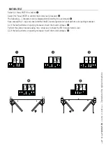
ILLUSTRATION OF THE SLOW-DOWN POINTS AND END-STROKE AREAS
The travel areas and slow-down and approach points are tested to comply with the parameters set forth by
Technical Regulations EN 12445 and EN 12453 for impact force compatibility of moving gate leaves.
A = Movement area at normal speed.
B* = Movement area at slowed-down speed.
C = Encoder intervention zone with movement inversion.
D = Encoder intervention zone with movement stopped.
E = Opening slow-down starting point for M2.
F = Closing slow-down starting point for M2.
G = Opening slow-down starting point for M1.
H = Closing slow-down starting point for M1.
I** = Closing approach starting point for M2.
L** = Closing approach starting point for M1.
M** = Opening approach starting point for M2.
N** = Opening approach starting point for M1.
O = Strike plates..
*
Minimum 600 mm from the strike plate.
** Set the closing-rest percentage for function F 39 - F 40 for the first motor (M1) and F43 - F44 for the second
motor (M2) so as to achieve a distance of less than 50 mm from the strike plate.


