background image

p.


30

 - M

an

ua

FA

00

441

-E

N

 - 0

8/

20

18 - © C

AM

E S

.p

.A

. - 

Tr

an

sla

tio

n o

f t

he o

rig

in

al i

ns

tru

ct

io

ns

F65

Wireless input 
RIO-EDGE [T1]

Wireless (RIO-EDGE) safety device associated to a function chosen among 
those available: P0 = TOTAL STOP, P7 = reopening during closing, P8 = 
reclosing during opening.
For programming, see the instructions that come with the accessory.

 This function only appears is the control board has been fitted with a 

RIO-CONN card.

OFF (default) / P0 / P7 / P8

F66

Wireless input 
RIO-EDGE [T2]

Wireless (RIO-EDGE) safety device associated to a function chosen among 
those available: P0 = TOTAL STOP, P7 = reopening during closing, P8 = 
reclosing during opening.
For programming, see the instructions that come with the accessory.

 This function only appears is the control board has been fitted with a 

RIO-CONN card.

OFF (default) / P0 / P7 / P8

F67

Wireless input 
RIO-CELL [T1]

RIO-CELL is associated to any function chosen among those available: P1 = 
reopening during closing; P2 = reclosing during opening; P3 = partial stop; 
P4 = obstruction wait.
For programming, see the instructions that come with the accessory.

 This function only appears is the control board has been fitted with a 

RIO-CONN card.

OFF (default) / P1 / P2 / P3

 / 

P4

F68

Wireless input 
RIO-CELL [T2]

RIO-CELL is associated to any function chosen among those available: P1 = 
reopening during closing; P2 = reclosing during opening; P3 = partial stop; 
P4 = obstruction wait.
For programming, see the instructions that come with the accessory.

 This function only appears is the control board has been fitted with a 

RIO-CONN card.

OFF (default) / P1 / P2 / P3

 / 

P4

U1

Entering users

Entering up to 250 users and associating to each one a function of choice 
among those included. Add users via a transmitter or other control device (see 
the paragraph called ADDING USERS WITH AN ASSOCIATED COMMAND).

1 = Step-step command (open-close) / 2 = Sequential command (open-

stop-close-stop) / 3 = Only open command / 4 = Partial command 

U2

Deleting users

Deleting a single user

OFF / ON 

= Enabling the deletion of single users.

U3

Deleting users

Deleting all users.

OFF / ON 

= Delete all users

U4

Decoding the code

Select the type of transmitter radio coding that you wish to save on the control 
board.

 When you select a radio coding, all saved transmitter are automatically 

deleted.


The TWIN coding lets you save multiple user with the same key (Key 

block).

= all (

default

) / 

2

 = Rolling Code / 

3

 = TWIN

A1

Motor type

For setting the type of gearmotor fitted onto the system.

= SWN20 - SWN25 (

default

) / 

= FA7024CB / 

= FTX20DGC

Summary of Contents for FTX20DGC
Page 1: ...Swing gate operator FTX20DGC FTX20DLC INSTALLATION MANUAL EN English FA00441 EN...

Page 2: ...p 2 Manual FA00441 EN 08 2018 CAME S p A Translation of the original instructions...

Page 3: ...1 3 2 3 2 3 1 2 1 3 2 3...

Page 4: ...spicious and unexpected behavior is experienced on the system call for qualified assistance MAINTENANCE WHEN CLEANING MAINTAINING AND REPLACING PARTS DISCONNECT THE OPERATOR FROM THE MAINS POWER SUPPL...

Page 5: ...upside down or onto elements that could yield to its weight If necessary add reinforcements to the fastening points check that the temperature range appearing on the operator is suited to the place o...

Page 6: ...nufacturer or by an authorized technical assistance center or in any case by qualified staff to prevent any risk During all phases of the installation make sure you have cut off the mains power source...

Page 7: ...o 2 m INTENDED USE This operator is designed to power swing gates for residential and apartment block use Any installation and or use other than that specified in this manual is forbidden LIMITS TO US...

Page 8: ...8 CAME S p A Translation of the original instructions DESCRIPTION OF PARTS 1 Cover 2 Control board protective cover 3 EMC02 card 4 Post brace 5 Gearmotor 6 Mechanical stops 7 Release lever 8 Lock 9 Co...

Page 9: ...by consumption W 7 Stand by consumption with the RGP1 W module 0 5 Maximum power W 140 Cycles hour 40 Operating temperature C 20 to 55 Torque Nm 180 Opening time at 90 s from 20 to 30 Gear ratio 1 168...

Page 10: ...e lengths differ from those specified in the table establish the cable sections depending on the actual power draw of the connected devices and according to the provisions of regulation CEI EN 60204 1...

Page 11: ...tallation with the gearmotor and transmission arms fitted to the left of the inward opening gate Fitting the gearmotor with the transmission arms to the right is done symmetrically Careful For outward...

Page 12: ...instructions Leaf opening arc A B C 90 140 210 540 0 50 90 140 200 510 75 200 90 150 180 510 225 250 110 200 220 480 0 50 Leaf opening arc A B C max 90 140 420 150 90 160 180 380 150 110 200 220 400 5...

Page 13: ...post brace FASTENING THE BRACES Marked the spots where the gate post brace and gate brace will be fitted The fastening measurements are listed in the paragraph titled CHECKING MEASUREMENTS AND APPLIC...

Page 14: ...olts Fit the plug into the socket on the gearmotor drive shaft PREPARING AND FASTENING THE OPERATOR Remove the operator s cover in the following way open the lock protection cap fit the trilobe key in...

Page 15: ...08 2018 CAME S p A Translation of the original instructions Fasten the driven arm to the transmission arm by using the pin the bolt and the washer Release the gearmotor and fasten the driven arm to t...

Page 16: ...e leaf Fit the second stop against the opposite side of the arm and fasten it with the bolt FASTENING THE MECHANICAL STOPS Release the gearmotor When opening Entirely open the gate leaf Fit the stop u...

Page 17: ...se adjust the endstop by turning the endless screw on the other endstop ESTABLISHING THE LIMIT SWITCH POINTS With the gearmotor released and the gate leaf closed adjust the closing limit switch grub s...

Page 18: ...inals for signaling devices 2 Gearmotors with encoder terminals 3 Control devices terminals 4 Safety devices terminals 5 CRP connection terminals 6 Terminals for transponder devices 7 Keypad selector...

Page 19: ...441 EN 08 2018 CAME S p A Translation of the original instructions 24 V AC DC control board power supply input 24 V AC DC max 40 W accessories power supply output ELECTRICAL CONNECTIONS The electrical...

Page 20: ...earmotors Connect the electric lock to the transformer s 17 V output and to terminal 5 on the control board WARNING To access the transformer you will need to remove the control board brace Transforme...

Page 21: ...programming the functions you can activate the OPEN STOP CLOSE STOP sequential command OPEN or CLOSE See function F7 STOP button NC contact For stopping the gate while excluding automatic closing To r...

Page 22: ...24 0 p 22 Manual FA00441 EN 08 2018 CAME S p A Translation of the original instructions BLUE BLACK BROWN BROWN BLACK BLUE BLUE BLACK BROWNE OPERATOR WITH GEARMOTOR OPERATORS BLUE BLACK BROWN Operator...

Page 23: ...il the gate is fully open again C2 close back up during opening When the gate is opening opening the contact triggers the inversion of movement until the gate is completely closed C3 partial stop Open...

Page 24: ...th the RIO CONN card the E 18 error message is displayed If the system has radiofrequency interferences the wireless system will inhibit the operator s normal operating mode and the E 17 error message...

Page 25: ...or at least one second Display The keys are for moving from one item to another increasing or decreasing a value opening and closing the gate only when testing The ESC button is for exiting menus canc...

Page 26: ...ic closing time function is activated OFF default C1 C2 C3 C4 C7 C8 F5 Safety test After every opening or closing command the board will check whether the photocells are working properly The safety te...

Page 27: ...ric lock The thrust time is set with F 26 OFF default ON F18 Additional light Output for connecting the additional light onto 10 E Flashing light it flashes when the gate is opening and closing Cycle...

Page 28: ...g the gearmotors speeds during calibration calculated as a percentage 20 20 of the maximum speed 50 50 of the maximum speed default 60 60 of the maximum speed F34 Travel sensitivity Adjusting obstruct...

Page 29: ...ly appears if the Encoder function is activated 1 1 of the gate travel 10 10 of the gate travel default F44 Closing approach point for motor M2 Adjusting as a percentage of the total travel the M2 mot...

Page 30: ...fitted with a RIO CONN card OFF default P1 P2 P3 P4 F68 Wireless input RIO CELL T2 RIO CELL is associated to any function chosen among those available P1 reopening during closing P2 reclosing during o...

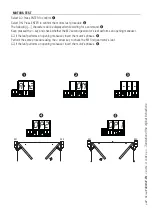
Page 31: ...ter powering up the system the first maneuver is always the opening In this phase the gate cannot be closed You will need to wait for the gate to completely open Immediately press the STOP button if a...

Page 32: ...st procedure The following characters will be displayed while waiting for a command Keep pressed the key and check whether the M2 second gearmotor s leaf performs an opening maneuver If the leaf perfo...

Page 33: ...d closing stops The mechanical end stops are obligatory Important During calibration all safety devices will be disabled Select A3 Press ENTER to confirm Select ON Press ENTER to confirm the automatic...

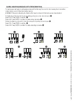
Page 34: ...p close stop 3 open 4 partial opening Press ENTER to confirm a number between 1 and 250 will start flashing for a few seconds Send the code from the transmitter or other control device such as a keypa...

Page 35: ...64 65 66 67 68 69 70 71 72 73 74 75 76 77 78 79 80 81 82 83 84 85 86 87 88 89 90 91 92 93 94 95 96 97 98 99 100 101 102 103 104 105 106 107 108 109 110 111 112 113 114 115 116 117 118 119 120 121 122...

Page 36: ...60 161 162 163 164 165 166 167 168 169 170 171 172 173 174 175 176 177 178 179 180 181 182 183 184 185 186 187 188 189 190 191 192 193 194 195 196 197 198 199 200 201 202 203 204 205 206 207 208 209 2...

Page 37: ...Manual FA00441 EN 08 2018 CAME S p A Translation of the original instructions DELETING SINGLE USERS Select U 2 Press ENTER to confirm Select ON Press ENTER to confirm the deletion procedure Use the ar...

Page 38: ...18 CAME S p A Translation of the original instructions SAVING AND UPLOADING DATA WITH THE MEMORY ROLL For saving user and system configuration data with the Memory Roll and for then reusing them on an...

Page 39: ...ncoder intervention zone with movement inversion D Encoder intervention zone with movement stopped E Opening slow down starting point for M2 F Closing slow down starting point for M2 G Opening slow do...

Page 40: ...ions FASTENING THE TRANSMISSION ARM PROTECTION Fit the protection under the operator and fasten it to the transmission arm using the screw FINAL OPERATIONS FASTENING THE COVER Once the electrical conn...

Page 41: ...PENING CONNECTIONS AND INSTALLING Following are the only things that change compared to a standard installation ERROR MESSAGE The error messages are shown on the display E1 The travel calibration was...

Page 42: ...opening inwards When closing Close the leaf Fit the second stop against the opposite side of the arm and fasten it with the bolt FASTENING THE MECHANICAL STOPS Release the gearmotor When opening Entir...

Page 43: ...ENC1 M2 N2 ENC2 p 43 Manual FA00441 EN 08 2018 CAME S p A Translation of the original instructions BLUE BLACK BROWN BLUE BLACK BROWN BLUE BLACK BROWN BLUE BLACK BROWN Operator fitted to the right and...

Page 44: ...ing materials cardboard plastic and so on should be disposed of as solid household waste and simply separated from other waste for recycling Always make sure you comply with local laws before dismantl...

Reviews: