


2
WARNING! Due to the high degree of complexity of the Camber FSR, proper assembly requires a
high degree of mechanical expertise, skill, training and specialty tools. Therefore, it is essential that
the assembly, maintenance and troubleshooting be performed by an Authorized Specialized Retailer.
WARNING! Many components on the Camber FSR, including, but not limited to, the rear
suspension and cable guides, are proprietary to the Camber FSR. Only use originally supplied
components and hardware at all times. Use of other components or hardware will compromise
the integrity and strength of the assembly. Camber FSR specific components should only be used
on the Camber FSR and not on other bicycles, even if they fit. Failure to follow this warning could
result in serious injury or death.
WARNING! Never modify your frame or bicycle in any way. Do not sand, drill, file, or remove parts.
Do not install incompatible forks or suspension parts. An improperly modified frame, fork, or
component, can cause you to lose control and fall.
CAUTION: Do not face or ream the bottom bracket shell! This can prevent proper installation
of the crank. Your Specialized frame does not require any bottom bracket shell pre-installation
preparation, as all surfaces have been precisely machined to specific tolerances at the factory for
proper interface with OSBB/BB30 compatible crankset.
In order to successfully build the Camber FSR bicycle, it is very important to follow the order of operations
as outlined in this manual. Modifying the order of assembly will result in a longer build process.
Inspect the fork, stem, seatpost and seat tube, to ensure that there are no burrs or sharp edges. Remove any
burrs or sharp edges using fine grit sandpaper.
All edges of the stem in contact with the steerer tube should be rounded out to eliminate any stress points.
WARNING! Burrs and sharp edges can damage the carbon and alloy surfaces of the components.
Any deep scratches or gouges in the stem or fork can weaken the components.
Specialized carbon frames use a 1 1/8” (41.8mm x 8mm x 45°) Campagnolo Standard compatible top and 1.5”
(52mm x 7mm x 45°) bottom bearing, except Demo frames which use a 1.5” diameter headset, top and bottom.
Ensure that replacement bearings are compatible with the Specialized headset specification. No tools are
needed for installation or removal of both bearings. Grease bearing surfaces before installation.
SEATPOST
Camber FSR frames have a 30.9mm seatpost diameter and require that the seatpost have a tolerance of
30.78mm to 30.95mm.
min
inse
rtio
n
1
A
B
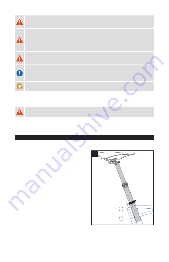
SEATPOST MINIMUM INSERTION:
To prevent damage to the frame and/or seatpost, it is important
to have a minimum amount of seatpost insertion in the seat tube.
This minimum insertion must meet the following requirements:
The seatpost must be inserted into the frame deep enough
so the minimum insertion/maximum extension (min/max)
mark on the seatpost is not visible (fig.1 A).
The seatpost must also be inserted into the seat tube deep
enough to be visible through the sight hole (fig.1 B), or if no
sight hole is present, the insertion must meet or exceed the
minimum measured insertion depth (fig.1 B) required by the
size of the frame (see below).
If the seatpost and frame minimum insertion requirements
differ from each other, always use the longer minimum
insertion. For example, if the frame requires 70mm, but the
seatpost requires 100mm, then 100mm is the minimum
insertion required.
•
SMALL / MEDIUM FRAME SIZE:
Minimum insertion 70mm
•
LARGE / X-LARGE FRAME SIZE:
Minimum insertion 100mm
If the seatpost is at the min/max mark and the seatpost is not visible through the sight hole or does not meet or
exceed the minimum measured insertion depth of the frame, the seatpost is not inserted deeply enough into the
Summary of Contents for FSR SERIES
Page 1: ...USER MANUAL...
Page 2: ......
Page 17: ......
Page 18: ......
Page 19: ......
Page 20: ...SPECIALIZED BICYCLE COMPONENTS 15130 Concord Circle Morgan Hill CA 95037 408 779 6229...


