background image


30

Call Records - Filters 

If you do not see the expected Call Records, make sure that the appropriate type record filters 
are checked.  Filters listed in Green below the call records will show.  Red listings types are not 
shown.  
The hardware must be set appropriately to deliver the expected records.  Use the 

Data Output 

Tab


to change the hardware output.  Your Caller ID application is designed for specific call 

record types.  Any additional data sent by the Vertex may prevent your application from 
functioning properly. 


Filters / Show Incoming 

When network parameters are configured correctly, the Vertex will always show Incoming 
records.  Be advised that the hardware can be set to only send Incoming Caller ID records at 
the "Start of Call" only, the "End of the Call" only, or both the start and end of call. 


Filters / Show Outgoing, Detailed, Call Accounting 

The Vertex hardware must be set to send Outgoing, Detailed, and Call Accounting records 
for this additional data to be shown in the Call Records screen.   


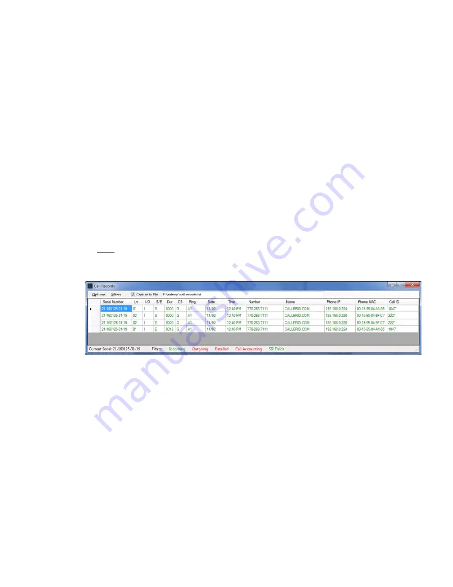
Filters / Show SIP Fields  

The Vertex hardware must be set to send SIP Fields for this option to be available. With the 
standard output format, when an inbound call rings multiple phones, a single start and end 
record is created for the call.  The Extra SIP field format creates a start and end of call record 
for each phone and sends additional fields appended to the records.  In the example below, 
one inbound call rang 2 phones. The phone with IP 192.168.0.224 answered for 18 seconds. 
One Start and one End of call record was sent for each phone. 


Filters / By Serial # 

This may be used if more than one Vertex was installed at the same location or both a Vertex 
and a Whozz Calling? analog unit were both reporting data over the network. 


Capture to File (option) 

This saves call records to a text file as they arrive into the VCT.  This will not log any calls 
that previously arrived before the option is selected.  Use Menu Selection: 

Options / Save

 to 

save call records already listed on the screen. 
 

Options / Capture to File Options 

Select whether you want to capture "Start of Call" records, "End of Call" records or both.


Monitor / Serial Data 

This option is available when the Vertex Data Output is selected for Serial Port.  If the Vertex is 
connected to the computer running VCT with a serial cable, this option may be used to view the call 
records sent.  It is required that a working serial port is available not used by any other software.  
Close any application that may be accessing the chosen serial port. If unclear which serial port is 
connected to the Vertex, use 

Tools / Port Scan

Summary of Contents for Vertex VoIP Caller ID

Page 1: ...Vertex VoIP Caller ID Version 2 0 12 01 2017...

Page 2: ...guration Key Parameters 9 VCT Main Tab 10 Serial Number 10 Firmware Version 10 Voice Channels Permitted 11 Unit Number 11 IP Setting 11 Unit IP Address 11 Gateway IP Address 11 Data Gateway MAC 11 SIP...

Page 3: ...ools Reset Hardware to Defaults 27 Tools Broadcast Connection 27 Tools Call Processing 28 Tools Find Vertex Port 28 Tools ARP Table 28 Tools Port Test 28 Tools Set Vertex to PC Time Unlocked Mode 29 M...

Page 4: ...evious Working Settings 37 Operational Troubleshooting Call Parking and Vertex Operation 37 Channels Exceeded message showing on Caller ID 38 Caller ID Name does not show correctly 38 Advanced Trouble...

Page 5: ...sents itself as an endpoint on the network 3 A single network connection carrying all VoIP traffic of interest must pass through the Vertex VoIP Bridge Ports to capture the incoming and outgoing telep...

Page 6: ...PRI and T1 feeds There are many types of architectures available using particular combinations of these and other items If you have a Managed VoIP system your IT person and or telephone switch provid...

Page 7: ...e specific port that connects to the Vertex Bridge Port 3 Power up the Vertex and wait until power light remains steady on The unit will attempt to negotiate DHCP in an effort to automatically obtain...

Page 8: ...vice simply contact your service provider Figure 1 Phones and Computers on the same Switch A typical Hosted VoIP network architecture is shown below with a Vertex unit connected If a separate gateway...

Page 9: ...and the Gateway Router is connected to the Network Switch through the VoIP Bridge ports on the Vertex Removal of the original connection allows all VoIP traffic to flow through the Vertex VoIP Bridge...

Page 10: ...OS application collects Caller ID via Ethernet connect the Vertex Management Port and your PC running the Vertex Configuration Tool VCT to the Data Subnet Router as shown in the diagram below Converse...

Page 11: ...d or telephone switch provider should know the details Note Although an Asterisk PBX is considered managed VoIP if the VoIP gateway is the same as the Data Gateway refer to the Hosted diagrams above F...

Page 12: ...y on in Appendix A Troubleshooting Vertex Configuration Tool VCT After hardware installation use the Vertex Configuration Tool VCT to set the necessary parameters specific to your network Note Turn of...

Page 13: ...tool 4 The Vertex Setup Wizard should be self guiding Help on setting up the Vertex manually using the main VCT tool follows Vertex Configuration Key Parameters Whether you use the step by step Verte...

Page 14: ...97 x Each numeric firmware edition has a compiled version for letters o n z x which indicates compatibility with your particular hardware revision When upgrading the version letter will remain the sa...

Page 15: ...gateways found Data Gateway MAC This must be specified to assure that the time and date are correct on call records The Vertex contacts a National Time Server to set its internal time clock If the IP...

Page 16: ...n is present Setting the Vertex time and date from the PC is the last resort This can be done from the Tools menu when the VCT is in an Unlocked Mode If the Vertex power is removed the time and date i...

Page 17: ...able to automatically set the correct parameters for most of our software partners Destination area Broadcast mode is used when your software application accepts Caller ID delivery via Ethernet For sm...

Page 18: ...when dialing an internal extension Format area Limited Format is used by some software packages that accept serial Caller ID The Limited format is not available with Ethernet delivery Comprehensive Op...

Page 19: ...ndividual Caller ID records to each computer The phone line number displayed on the computer for each call will match the line appearance button on the VoIP phone For example if Station A is on a call...

Page 20: ...it until all your phones are detected and select Stop Detection or you can simply let the 2 minute process time out If all your phones are not detected check whether the undetected phones are operatin...

Page 21: ...he Add to Routing Table button Enter a workstation name and the IP address on the computer associated with that phone Add the remaining detected phone entries to the Routing Table Select the Save and...

Page 22: ...18 The main Station Routing tab will display your entries...

Page 23: ...ally turned off Consequently VCT and other applications will not show standard call records VoIP Signaling Format Normally the SIP Invite header includes the Session Description Protocol SDP The Verte...

Page 24: ...5 You can send the file to CallerID com You will need to follow up with an Email stating the problem you are having and when the file was uploaded Bootup Radio Button This helps troubleshoot DHCP DNS...

Page 25: ...t seeing a SIP Invite to that phone We have encountered locations where some phones are communicating via unencrypted SIP while other phones in the same ring group are using alternative signaling Furt...

Page 26: ...name is extracted from the header by locating the first quote and then storing the next 15 characters In this Example the Name will be displayed as ELLIJAY GA If the text is less than 15 characters th...

Page 27: ...from the SIP Gateway to each of the 2 phones ringing If the Gateway MAC is needed select the Invite record and use the Set to SIP Gateway button next to From heading If an outbound call is captured in...

Page 28: ...ngs The Vertex hardware saves all settings within non volatile memory We recommend saving these parameters in a file on the PC If the Vertex needs to be replaced or repaired the settings can be loaded...

Page 29: ...to the IP address of the Vertex We recommended assigning a static IP on the Vertex hardware to prevent DHCP from changing the IP address The Location Manager can also be used to connect to the hardwar...

Page 30: ...kground The parameters from the last location will be shown in the foreground The highlighted buttons on each tab will show if any differences are present This allows easy comparison of two units In o...

Page 31: ...eset the hardware to defaults after boot up If so remember to set them back down before subsequent reboot in order to save any changes made Tools Reset Hardware to Defaults This option is password pro...

Page 32: ...the Vertex parameters into the VCT using that port Tools ARP Table Results show when user has administrator rights If the Vertex is set for Static IP you can set the Data Gateway MAC within the VCT by...

Page 33: ...F and On Hook N events will be shown in this column S E Start of Call or End of Call record End of Call records must be enabled on the Data Output Tab to display here Dur Duration of phone call in se...

Page 34: ...a single start and end record is created for the call The Extra SIP field format creates a start and end of call record for each phone and sends additional fields appended to the records In the exampl...

Page 35: ...ed properly Tools Upload You can upload your resulting call records to CallerID com for analysis If so please follow up with an Email stating your issue and include the Serial Number of the Vertex Mon...

Page 36: ...option the VCT is unlocked denoted by U Tip A right mouse click on the L will unlock password protected options 3 4 Location Last Command Label Button Location shows the method of UDP communication w...

Page 37: ...1 4 H Actual Unit Weight 0 81 lbs Size of Entire Product Box 12 x 10 x 6 Weight of Entire Product w Peripherals 2 2 lbs Shipping Weight 3 lbs Dimensional Shipping Weight 7 lbs Electrical Supply Volta...

Page 38: ...purchase date or serial number 5 A return material authorization RMA number is required before returning equipment for repair All repairs are covered under a 90 day limited warranty Please contact Ca...

Page 39: ...m the SIP Gateway MAC the call is detected as inbound If the Invite is sent from a MAC other than the SIP Gateway MAC it reports the call as outbound Setup Troubleshooting Vertex Configuration Tool VC...

Page 40: ...he Vertex is problematic If both amber lights are off on the VoIP bridge ports then most likely both network appliances are incompatible Three options are available to help correct this issue Solution...

Page 41: ...parameter files each time you exit the application If you are using the VCT program from the same PC that configured the Vertex to a working condition then a backup file of parameters will be availab...

Page 42: ...can be used to identify parked callers Once a call is parked the FB used to park the call lights up Upon retrieval the light goes off When a parked call is retrieved from a Private Parking space the...

Page 43: ...omputer using a VPN connection the Vertex must respond via Unicast If DIP switch 1 is up ON the Vertex will send back all command responses and processed call records via Unicast to the IP address of...

Page 44: ...n Tools Port Test 6 Select the Test Now button The results will show the functionality of all 3 ports on the Vertex Port 1 is the Management Port Port 2 is the VoIP Bridge Port marked Towards Gateway...

Page 45: ...he Vertex responds back with all its parameters This option instructs the hardware to simply send its parameters every second regardless of the VCT command UUUD The Vertex default address is 192 158 1...

Page 46: ...ure feature in the Advanced Tab Analyzing the network packets requires an application such as Wireshark 1 Make sure any VoIP phone traffic or critical internet traffic is not in progress 2 Disconnect...

Page 47: ...ertex is incompatible with the following VoIP providers since they do not communicate using standard unencrypted SIP signaling List as of Jan 1 2018 RingCentral Belmont CA Shoretel Inc Sunnyvale CA ac...

Reviews: