Calian SatService sat-nms ACU2-19V2 User Manual Download Page 13

connected either to pin xxx at the ACU or to the ground at the encoder housing, never at both
ends. The power supply outputs are internally fused. Be aware not to cause a short circuit. If this
happens, the unit has to be opened and the fuse has to be replaced. Do not open the unit by
yourself, you will loose warranty in that case.

pin

signal

description

type

15

Clk+

SSI clock

OUT

16

Clk-

SSI clock

OUT

17

SHLD

Shield

21

Data+

SSI data

IN

22

Data-

SSI data

IN

23

SHLD

Shield

24

+24V

encoder power supply

25

0V

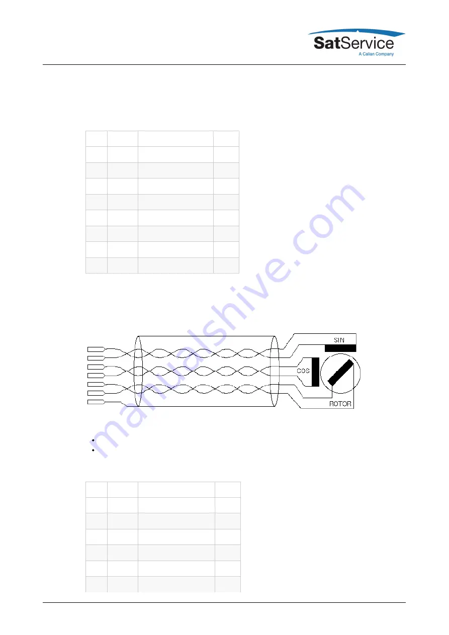
Resolver interface J7, J8

The ACU resolver interface is designed for resolvers with an impedance of 100 Ohms or more
and transfer factor 0.5. The interface applies 4Veff / 2000Hz to the resolver drive coil. It expects
2Veff at the sine / cosine inputs at the maximum positions.

When connecting a resolver to the ACU, please consider the following:

Use a shielded, twisted pair cable.
Connect the cable shield either to the case of the DSub9 connector or to the ground at the
resolver housing. Never connect the shield at both ends, this will introduce a ground loop
and cause a significant degradation of the resolver's accuracy.

pin

signal

description

type

1

SHLD

Shield

2

REF

drive signal to resolver

OUT

3

COS-

resolver COS

IN

4

SIN-

resolver SIN

IN

5

COS

resolver COS

IN

6

SHLD

Shield

(C) 2022, SatService GmbH

www.satnms.com

ACU2-19V2-UM-2209 Page 12/99

Summary of Contents for SatService sat-nms ACU2-19V2

Page 1: ...ACU2 19V2 User Manual Version 2 0 014 Copyright SatService Gesellschaft f r Kommunikationssysteme mbH Hardstrasse 9 D 78256 Steisslingen satnms support satservicegmbh de www satnms com www satserviceg...

Page 2: ...P Address 19 4 3 2 Angle detectors 20 4 3 3 Driver Interface 20 4 3 4 Pointing Tracking 20 4 3 5 Backup of ACU settings 21 5 Operation 22 5 1 The Web based User Interface 23 5 2 Antenna Pointing 25 5...

Page 3: ...1 The sat nms Steptrack Algorithm 86 8 3 2 ACU and Beacon Receiver 87 8 3 3 Smoothing 88 8 3 4 Steptrack Parameters 89 8 4 Adaptive Tracking 90 8 4 1 The sat nms Adaptive Tracking Algorithm 92 8 4 2...

Page 4: ...l which is used to predict the antenna position This reduces the step track failures and provides continuous operation in case of a beacon receive failure In the Program Tracking Mode the antenna foll...

Page 5: ...y 6 8 Set az el pl by editing Numeric Parameters 7 Remote Control 7 1 General command syntax 7 2 The TCP IP remote control interface 7 3 The RS232 remote control interface 7 4 Parameter list 7 5 One l...

Page 6: ...unt case for indoor use For detailed description please refer to the sat nms documentation CD or www satnms com Main benefits of the sat nms ACU are The ACU outdoor unit is able to act as a standalone...

Page 7: ...e the Internet Explorer on MS Windows based computers The user interface design is straight forward and clearly structured Operating the ACU is mostly self explanatory Nevertheless the Operation chapt...

Page 8: ...visible damage Ensure that the cabinet is proper connected to the protective earth conductor The circuit breaker that fuses the mains for the sat nms ACU has to switch off all phases AND the neutral...

Page 9: ...rview to the interfaces of sat nms ACU19V2 For more detailed informations refer to the chapters below The following pictures show the front and rear view of the unit sat nms ACU19V2 Front panel view s...

Page 10: ...h and elevation axis and a resolver interface at polarisation axis 3 6 Alarm interfaces The sat nms ACU19V2 provides a dry contact Alarm interface Please refer to chapter Interfaces to the antenna Pin...

Page 11: ...chapters show the standard pin configuration If you have a non standard version please refer to the documentation enhancement that shows the pin descriptions of it 4 2 1 Connector Layout Below the con...

Page 12: ...D OUT 7 SHLD Shield J6 J7 and J8 Polarisation and Az El Angle encoders Connector Type J7 J8 D Sub25 male J6 D Sub9 male The sat nms ACU19V2 provides the possibility to connect two different types of a...

Page 13: ...esolvers with an impedance of 100 Ohms or more and transfer factor 0 5 The interface applies 4Veff 2000Hz to the resolver drive coil It expects 2Veff at the sine cosine inputs at the maximum positions...

Page 14: ...ub9 connector or to the ground at the resolver housing Never connect the shield at both ends this will introduce a ground loop and cause a significant degradation of the resolver s accuracy pin signal...

Page 15: ...esolver SIN IN 5 COS resolver COS IN 6 SHLD Shield 7 SHLD Shield 8 REF drive signal to resolver OUT 9 SIN resolver SIN IN TB1 Alarm Connector Type D Sub9 female TB1 provides a dry contact Alarm Interf...

Page 16: ...and Common IN 4 LP Cmd OUT LP Command Output OUT 5 n c not connected 6 CP Ind A CP Indicator Anode IN 7 CP Ind K CP Indicator Cathode IN 8 LP Ind A LP Indicator Anode IN 9 LP Ind K LP Indicator Cathod...

Page 17: ...K Aux 5 8 Input Cathode only 4th Axis Option IN 18 AUX 5 8 K Aux 5 8 Input Cathode only 4th Axis Option IN 19 AUX 5 8 K Aux 5 8 Input Cathode only 4th Axis Option IN 20 Pl Limit CW IPl Limit CW IN 21...

Page 18: ...e type with IEC connector As they are wide range types it is possible to connect nearly all worldwide available single phase mains Please refer to chapter Specifications for more detailed informations...

Page 19: ...lf Mains power at connector J12 A Computer running a Microsoft Windows operating system equipped with CD ROM drive and Ethernet network card A CAT5 crossover network cable or an Ethernet hub and stand...

Page 20: ...his field blank Be sure that the DHCP mark is unchecked the other values have to be set as shown on the picture Finally click to the Yes button to set the new parameters at the ACU Now the IP configur...

Page 21: ...soft limits to the desired values e g 1 degree before the hardware limit switch is activated 4 3 4 Pointing Tracking Now the setup of all interfaces to the antenna is done By this everything is prepa...

Page 22: ...in the drop down list The file will immediately be copied to the location shown on the left side If you have saved targets you might backup them in the same way They are named targetXX txt XX represe...

Page 23: ...address field where you normally enter the URL of a web page you want to see type in the IP address of the sat nms ACU you want to control The ACU shows a web page consisting of a navigation bar at t...

Page 24: ...the antenna a small step to the indicated direction For azimuth and elevation small step and large step buttons are provided A small step is the angle defined with the XX step delta parameters at the...

Page 25: ...PPED is displayed Finally if the ACU recognizes the activation of a limit switch the orange colored label LIMIT is displayed in this field If the ACU is in standby mode STANDBY ist displayed for all a...

Page 26: ...information about the model of antenna satellite movement the ACU has calculated from the step track data M model The complexity of the model the ACU uses small medium large With a small amount of tra...

Page 27: ...et table itself displays 20 of the stored target memories By clicking the icons in the table settings may be stored recalled or deleted Go If a memory location has stored a pointing the table shows a...

Page 28: ...itial pointing mode and the target orbit postion Set the Level threshold in the tracking menu to a large value e g 100dB If TLE or I11 Parameter for the satellite available Menu Orbit Data choose the...

Page 29: ...you can use the TLE or I11 Tracking to find the target especially for inclined orbit satellites is this recommended If the step adaptive tracking could be established recalc the Level Offset in the Tr...

Page 30: ...a moves along a path calculated from a TLE ephemeris data set There are no optimization steps and no receive signal is required for such an optimization I11 The antenna moves along a path calculated f...

Page 31: ...TIVE This mode works very much like ON but with step track based tracking modes the values for the satelite s orbit position and inclination are re calculated from the recorded tracking data every thr...

Page 32: ...If the relative beacon level falls below this threshold value the ACU does not perform a step track cycle If the level falls below the threshold during the steptrack cycle the cycle gets aborted If t...

Page 33: ...y to move the antenna again with the next tracking cycle If the antenna is really blocked the ACU will try to move the antenna every tracking cycle This increases the probability to keep the antenna f...

Page 34: ...receiver parameters are not available if the ACU works with a 3rd party beacon receive RF receive frequency This is the receiver s nominal receive frequency Depending on the LO frequency settings made...

Page 35: ...result due to the LNB s band filter The measured noise level may be too low in this case 3 You should verify with a spectrum analyzer that no signal disturbs the noise measurement at the selected freq...

Page 36: ...splays the electrical logical level of all inputs and outputs of the ACU This helps you to install the ACU or to identify a malfunction of peripheral components The layout of this page differs slighty...

Page 37: ...the coefficients of the actual model in two lines at the bottom of the text page The number of coefficients displayed depends on the size of the model SMALL a0 a1 a2 1 MEDIUM a0 a1 a2 a3 a4 2 LARGE a...

Page 38: ...the Antenna controlled by this ACU Date time By changing this value you can set the internal clock of the ACU The clock is set as soon you click to the Submit button in the data entry dialog The most...

Page 39: ...CAB OPEN FAULT if this input is active ON treats this input as an indication that the ACU is controlled by an analog handheld unit Use hub fault as summary limit This controls the way the hub fault i...

Page 40: ...ffset from a known pointing 1 Set the calibration scale gear ratio for the axis this calibration parameter is described with the next paragraph 2 Set the soft limits of the axis to preliminary values...

Page 41: ...s to motor to be blocked and switches it off This motor timeout fault must be reset by the operator to release it A timeout value 0 disables the timeout Lower limit The minimum target value accepted a...

Page 42: ...rom the ACU itself by FTP user service password service The file ACUODM MIB contains all necessary information SNMP read community Sets the SNMP community string expected for read access The default i...

Page 43: ...t still supported in the ACU software Remark The ACU RMU and ACU19xx Versions have already a build in frontpanel control and therefor there is no additional Handheld interface available at these units...

Page 44: ...of the ACU without the need of a Ethernet connection The interface to the ACU ODM is a serial RS422 link The integrated display shows angle values of all 3 axes and beacon level There is possible to c...

Page 45: ...nce The start up screen that shows the installed software version is displayed for a few seconds After that the menu for controlling the antenna is displayed automatically Operation Emergency STOP sto...

Page 46: ...d stand alone you are free to enter any text here Target memories are saved and recalled by number hence it does not matter if there are duplicate target names If however the ACU ODM is controlled by...

Page 47: ...this position has been reached the tracking selected by the tracking mode is started ORBIT The antenna s Az El Pol angles are calculated from the satellite s orbit position stored in the recalled targ...

Page 48: ...hould check if the beacon frequency is set properly The frequency must be the true receive frequency at the antenna entered in MHz not an L band frequency or other IF Beacon frequency This parameter t...

Page 49: ...or worse after a test step If the delay is too long the impact of fluctuation to the measured level grows and may cover the small level difference caused by the test step With the sat nms LBRX beacon...

Page 50: ...s a reference to the memory location where the TLE parameter are stored hence if the parameters at this location are changed the ACU automatically uses the changed parameters max TLE I11 age If the ep...

Page 51: ...particular satellite The Orbital Data Editor page shows a table of all 99 datasets of a type TLE or I11 with their memory number and their name Unused datasets have no name assigned they are shown wi...

Page 52: ...ng process leaves the stored values unchanged You are returned to the orbital data selection page SAVE This saves the edited values and returns to the orbital data selection page If the ACU actually u...

Page 53: ...0 0 0 9996 2 20776 13 9269 3 9374 0002599 315 1892 36 0996 1 00268879111281 TDRS 5 1 21639U 91054B 21039 72583038 00000073 00000 0 00000 0 0 9991 2 21639 14 2519 8 6689 0026423 358 2787 225 7580 1 002...

Page 54: ...tion page If the ACU actually uses the I11 dataset with this number for tracking the new dataset will be used with the next tracking cycle SAVETO This saves the edited values to the memory location se...

Page 55: ...TELSAT 12 WEST B 2020 04 29 00 00 00 12 4836 0 0024 0 000200 0 0337 0 0005 0 0746 0 0001 347 4772 0 5068 EUTELSAT 16A 2020 04 29 00 00 00 15 9867 0 0034 0 000108 0 0047 0 0004 0 0584 0 0004 15 9675 0...

Page 56: ...ws the I11 ephemerides list The heading I11 Elements is shown at the top left Now click to the re read the I11 TXT file link at the bottom of the page The I11 data is now imported from the I11 TXT fil...

Page 57: ...Move the elevation up down Move the elevation east west 1 and 3 Select the STANDBY Operation Mode For 4 axis models of the ACU the keys 4 to 6 also have a special function 4 Move the polarization 2 c...

Page 58: ...he following messages may be displayed at the corresponding position in the display At the corresponding angle position FAULT General ACU Fault TIMEOUT Motor moves but the position encoder does not re...

Page 59: ...ELECT TRACKING MODE menu you can change the tracking mode as shown below OFF STEP ADAPTIVE PROGRAM For detailed information about tracking please refer to chapter 8 3 Step Tracking chapter 8 4 Adaptiv...

Page 60: ...l function 4 Move the polarization 2 counterclockwise 5 Switch the polarization angle display between polarization 1 and 2 6 Move the polarization 2 clockwise The antenna will as long move as longe a...

Page 61: ...the parameter it receives last 7 1 General command syntax The ACU knows a number of parameters each identified by a parameter name To set a certain parameter to a new value a message name value has to...

Page 62: ...is rmt hence assuming the ACU is listening to the IP address 10 0 0 1 requesting a document with the URL http 10 0 0 1 rmt levl Will let the ACU reply the actual beacon level in a one line text docume...

Page 63: ...13 10 There is no echo for characters entered hence this protocol easily may be used for computer based remote control This setting is also used for allowing communication to an optional frontpanel di...

Page 64: ...AZ Pre scale offset apos r o 180 000 180 000 AZ Pointing araw r o 00000000 FFFFFFFF AZ raw pointing asca 0 000000 100000 000000 AZ Calibration scale asen SSI 13B SSI 13G SSI 17B SSI 17G SSI 18B SSI 1...

Page 65: ...evel threshold caps r o 00 FF Software capabilities 1 cmod DISABLED ENABLED Linear Circular switch cnmf MHz BCRX Noise measurement frequency cnmi sec BCRX Noise measurement interval coha OFF ON Use ca...

Page 66: ...iver type eofs EL Pre scale offset epoc r o Model epoch epos r o 0 000 90 000 EL Pointing eraw r o 00000000 FFFFFFFF EL raw pointing esca 0 000000 100000 000000 EL Calibration scale esen SSI 13B SSI 1...

Page 67: ...I11 parameter select 3 ibit 00000000 FFFFFFFF Input bits described below ibi2 0000 FFFF Extended input bits described below icty NONE Inclinometer type 4 incl Satellite inclination inpo STORED POSITIO...

Page 68: ...ver 1 address ntp2 NTP server 2 address obit 00000000 FFFFFFFF Output bits described below obi2 0000 FFFF Extended qutput bits described below orbt 180 000 180 000 E Orbit position pcal 3600 000 3600...

Page 69: ...ue ptot 0 32000 msec PO Motor timeout qcal 3600 000 3600 000 PO2 Calibration offset 11 qclc Calculate offset from Pol 2 value 11 qhys 0 000 10 000 PO2 Pointing hysteresis 11 qinv NORMAL INVERTED PO2 S...

Page 70: ...ve target scmp character string BCRX Spectrum compensation scnt r o 0 65535 Save count scon SNMP system contact sdly sec BCRX Signal search delay slee r o 0 65535 sec Sleep time up to the next trackin...

Page 71: ...tion offset tflt r o 00 FF Tracking fault bits described below tgac ACK NEW Acknowledge position change tgnr r o 1 199 Loaded target number 1 unknown tgtd r o 0 1 Target tainted thrh dBm BCRXAlarm thr...

Page 72: ...e sync alarm 0 OK 1 FAULT 2 using NTP2 because NTP1 does not answer ttle 0 99 TLE parameter set selected in target wcom SNMP write community wdog OFF ON ON Sends a heatbeat to the AUX 8 output xipt 1...

Page 73: ...freq in the target editor eftri same as ftri Copy of ftri in the target editor eftrk same as ftrk Copy of ftrk in the target editor eftrw same as ftrw Copy of ftrw in the target editor eincl same as...

Page 74: ...target editor essth same as ssth Copy of ssth in the target editor etaof same as taof Copy of taof in the target editor etcyc same as tcyc Copy of tcyc in the target editor etdly same as tdly Copy of...

Page 75: ...l 2 ACU variants with compass support provide other choices beside NONE for this parameter 3 To set a I11 parameter set from extern first select the parameter set to edit 0 99 by writing the parameter...

Page 76: ...one ON The ACU calculates and commands the pol angle with each tracking cycle With TLE or I11 it calculates the angle from there with steptrack modes it calculates the pol angle from the satellite s o...

Page 77: ...ut 22 PLTOT polarization timeout 23 TIMEOUT timeout summary bit 24 TRKPEAK peaking in progress 25 LOWBEAC low beacon signal 26 BCRXFLT beacon receiver fault 27 LIMIT limit switch summary 28 AZSTOP azi...

Page 78: ...ast significant bit bit number 31 the most significant bit in this number no name description 0 OUT_AZ_FWD azimuth motor forward 1 OUT_AZ_REV azimuth motor reverse 2 OUT_AZ_SPD1 azimuth motor low spee...

Page 79: ...ed for beacon receiver frequency select 29 OUT_BCPR4 reserved for beacon receiver frequency select 30 OUT_AUX7 not used 31 OUT_AUX8 not used The meaning of the FWD REV motor control outputs depend on...

Page 80: ...ptive tracking mode the acoe ecoe commands may be used to read the coefficients of the actual model The coefficients are returned as a comma separated list of numbers in scientific notation The number...

Page 81: ...e typical sequence to update a TLE parameter set is as follows 1 Select the number of the TLE parameter set to write to by setting the tles parameter to this number 0 99 2 Write the TLE line 1 to the...

Page 82: ...apos 174 688 epos 31 456 ppos 34 5 atar 174 700 etar 31 500 ptar 34 5 blev 64 33 temp 63 5 obit FFFF0000 ibit FFFF0000 4 axis version of the ACU return an extended string with the information for the...

Page 83: ...geable interfaces for several types of position sensors Position sensor interfaces may be selected individually for each axis This gives a maximum of flexibility for application where the sat nms ACU...

Page 84: ...y add the pre scale offset 5 Convert to degrees 6 If the calibration scale is nonzero multiply by the calibration scale 7 Add the post scale calibration offset 8 For the azimuth axis add the antenna c...

Page 85: ...n modes to control a motor driver They are called DIR START and DUAL START In DIR START mode the FWD signal switches the motor on off the REV signal controls the motor direction This is the configurat...

Page 86: ...he satellite move it a small amount to the other site and finally point the antenna to that position where the signal is the strongest The sat nms ACU uses an optimized variant of this method which le...

Page 87: ...time than for a geostationary satellite 8 3 2 ACU and Beacon Receiver To perform a step track the ACU requires the actually measured beacon level as a rate of the received signal quality and therefore...

Page 88: ...at the beacon receiver these values may be adjusted too a preferable scale is 0 5V dB for 20dB usable range The offset should be adjusted that the receive level at clear sky conditions leave a headroo...

Page 89: ...ust have assigned IP addresses in the same subnet The LBRX beacon receiver must be configured for the correct LO frequency The displayed receive frequency must be the true RX frequency rather than the...

Page 90: ...acking step seems to be completely out of range you should check if the beacon frequency is set properly The frequency must be the true receive frequency at the antenna entered in MHz not an L band fr...

Page 91: ...ata points used to evaluate a model is limited the measurements values are distorted due to inaccuracy and noise The more complicated a model is the more susceptible it is to noise For practical usage...

Page 92: ...s half 3dB beam width to evaluate this measure The ACU presents this figure as a percentage value The ACU selects the adaptive tracking model following a scheme as illustrated in the diagram above Bel...

Page 93: ...he ACU raises a fault if at least one axis exceeds the threshold value If this happens three consecutive times the models gets reset all data in the tracking memory gets marked invalid 8 4 2 The Track...

Page 94: ...With this function you should keep in mind that the tracking memory contents becomes useless after about 24 hours 8 4 3 Adaptive Tracking Parameters The behaviour of the adaptive is adjustable with a...

Page 95: ...Setting it to 0 switches the threshold monitoring completely off 8 4 4 Hardware Protective Mode Spindle Save Mode The so called Spindle Save Mode will reduce the tracking cycles and will therefore in...

Page 96: ...ACU must be set precisely to make the feature work as expected 8 5 2 File Format The program txt file is a plain text file containing a three or four column table Empty lines are ignored comments sta...

Page 97: ...eliver data in this format The data format and the mathematical model for this data is Intelsat proprietary and defined in the document IESS412 8 7 1 Intelsat eleven Parameter Prediction I11 The analy...

Page 98: ...the antenna will stop the execution and an alarm will be displayed in the pointing screen If the calculation failed an invalid TLE Alarm will be displayed 8 8 Polarization Prediction The polarization...

Page 99: ...om the tracking also the dynamic of the satellite movement up or down the sat nms ACU cannot start the polarization prediction immediately after setting the polarization prediction to ON or ADAPTIVE i...

Page 100: ...s selectable sat nms LBRX or analog voltage input Analog voltage input 0 to 10V Option Tracking Accuracy Better than 5 of receive 3dB beamwidth RMS The encoder coupling and alignment error should not...

Reviews: