background image

Hi Flow Stroller Technical Service Manual • PN 14314465 Rev 

F

32

H

i F

lo

w S
tr

oller

Repair Procedures

X

RP27 – Case Cleaning

a. Clean using household glass cleaner or Simple Green D and

lint-free cloth. Do not get glass cleaner inside case or onto any 

plumbing components. Simple Green D is available at www.

simplegreend.com

b. If necessary, a soft bristle brush can be used to help remove dirt 

and debris. If desired, Caire, Inc. Technical Service can sup-

ply a specific list of additionale reccommended cleaning tools.

c. Allow unit to dry thoroughly before filling.

RP28 – Normal Evaporation Rate Test

a. Fill unit following procedure found in the Patient Operating

Instructions (POI).

b. Push button and check that all 8 LEDs are on, or verify that

the spring scale reads full.

c. Check for leaks in QDV and vent valve.

d. Let unit sit 16–18 hours.

e. Make sure FCV and vent valves are closed.

f. Do not move unit during this time.

g. If the Hi Flow is at least half full (4 LEDs), the unit passes.

Maximum loss rate prior to dewar servicing is 1.75 lbs./day

(0,8 kg/day).

NOTE: Clean case only after unit is empty and warm. Do not 

clean in oxygen enriched atmosphere.

NOTE: Only use disinfectants or cleaning agents approved 

for use with this equipment by CAIRE such as Sporicidin®, 

HydroPure®, Hydroklean®, or others as specified by CAIRE.

RP2

9

 – 

Relief Valve Test

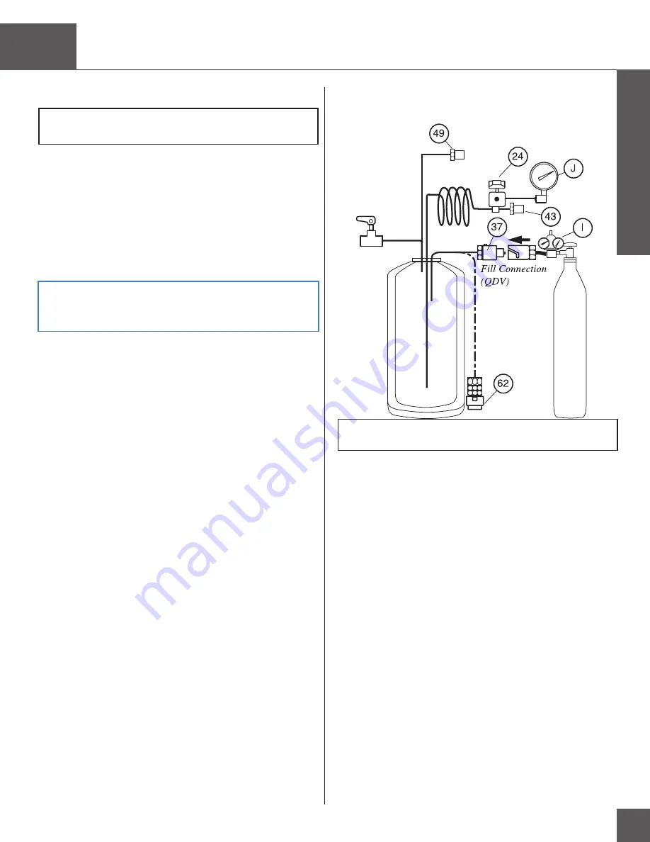
FIGURE 

21

Relief Valve Test

WARNING:

 The unit must be empty, warm and vented before 

starting procedure.

a.

Remove case (RP4).

b.

Assemble pressure gauge (Item J) and adapter assembly.


Thread


hose barb onto pressure gauge. Push tubing onto hose


barb


and


attach with clamp.

c.

Assemble oxygen regulator, hose and pneumatic adapter.


Connect assembly to oxygen gas source. Connect pneumatic


adapter to unit QDV (Item 37

 or 62

).

d.

Slowly begin increasing pressure to between 1,

35-1,4

8

bar/

19,7-2

1

,

psig. PRV (Item 

49

) should begin venting

(audible noise  will be heard or bubbling will be seen if leak


testing).

e.

Slowly begin decreasing the pressure until the PRV (Item

 49)


closes, meaning the audible noise is no longer heard or the


bubbling is no longer seen if leak testing. The pressure at


which


the audible noise or bubbling is no longer seen should


be


greater than 1.

24 

bar/

18

psig

.

f.

Hold PRV (Item 49) closed (with finger) and increase pres-sure 

to 1,9-2,3 bar (27-33 psig). SRV (Item 43) must begin


open 

(audible venting and/or bubbling of leak test solution).

g.

Slowly begin decreasing the pressure until the SRV 

(Item 43)


closes, meaning the audible noise is no longer heard or the


bubbling is no longer seen if leak testing. The pressure at


which


the audible noise or bubbling is no longer seen should


be


greater than 1,

68 

bar/2

4,3

 psig

.

h.

Slowly begin decreasing the pressure


in order to release the


finger from the PRV.

Summary of Contents for Hi Flow Stroller

Page 1: ...Hi Flow Stroller Technical Service Manual...

Page 2: ...structions SRV Secondary Relief Valve N2 Nitrogen Gas O2 Oxygen Gas TF Top Fill SF Side Fill DF Dual Fill PTFE Polytetrafluoroethylene Teflon Definition of Terms WARNING Description of a condition tha...

Page 3: ...t Description 3 IV Specifications 4 V Safety 5 VI Theory of Operation 10 VII Unpacking and Setup 12 VIII Operation 12 IX Maintenance 13 X Troubleshooting Repair Procedures Table of Contents 15 Trouble...

Page 4: ...C 300 F 2 Breathing Circuit This circuit consists of the manifold as sembly fixed orifice rotary flow control valve FCV and vaporizing coil It withdraws liquid oxygen from the cryo genic container war...

Page 5: ...e or 10 of flow setting whichever is greater Normal Evaporation Rate lbs day kg day 1 2 0 54 Operating Pressure PSIG Bar 20 1 4 Primary Relief Valve Setting PSIG Bar 19 7 21 5 1 35 1 48 Secondary Reli...

Page 6: ...esigned into the unit and safe operations are anticipated it is nec essary that all distributor personnel carefully read and fully un derstand WARNINGS CAUTIONS and NOTES throughout the manual Periodi...

Page 7: ...rgy only for internal function CISPR 11 Therefore its RF emissions are very low and are not likely to cause any interference in nearby electronic equipment RF emissions CISPR 11 Class B Harmonic emiss...

Page 8: ...supply lines DC powered device IEC 610004 4 1 kV for Not applicable input output lines No data input output lines 1 kV line s Surge to line s Not Applicable Not Applicable IEC 61000 4 5 2 kV line s D...

Page 9: ...electromagnetic site surverya should be less than the compliance level in each frequency rangeb Interference may occur in the vicinity of equipment marked with the following symbol NOTE 1 At 80 MHz an...

Page 10: ...0 MHz 80 MHz and 800 MHz 800 MHz to 2 5 GHz d 1 2 P d 1 2 P d 2 3 P 0 01 0 12 m 0 12 m 0 23 m 0 1 0 38 m 0 38 m 0 73 m 1 1 2 m 1 2 m 2 3 m 10 3 8 m 3 8 m 7 3 m 100 12 m 12 m 23 m For transmitters rate...

Page 11: ...oxygen saturation pressure can seriously affect the overall efficiency and operation of the Hi Flow Stroller a If the saturation pressure of the liquid in the fill source is greater than 30 psig 2 1...

Page 12: ...the mount ing bracket The meter is powered by an internal battery offering an esti mated battery life of 5 years or more at 30 actuations per day The meter has a low battery LOW BATT indicator which...

Page 13: ...not exceed the maximum prescribed flow rate 1 To remove the flow control knob firmly grip and pull straight up away from the portable 2 Remove the flow rate decal number disc Item 21 3 Remove the 2 P...

Page 14: ...if soiled 2 Full Unit a Fill vent full of LOX b Check for audible or visual leaks in QDV and vent valve c Verify that the meter reads full 8 LED 3 Check Efficiency of Unit a Allow the unit to stabiliz...

Page 15: ...rol knob turns easily with firm detent feel b Condensation pad is not soaking wet or excessively dirty c QDV pin not bent side fill only 2 Verify that the meter reads the correct liquid level 3 Check...

Page 16: ...fold Assembly RR 26 RP10 Resolder Feed Thru Wire 26 RP11 Clean Dry Probe Dewar 27 RP12 LOX Fill 27 RP13 Liberator Lip Seal RR Side Fill 27 RP14 Empty and Warm 27 RP15 QDV RR Side Fill 27 RP16 QDV RR T...

Page 17: ...troller Troubleshooting Chart X Introduction 1 These procedures are designed to be performed only by qualified personnel with proper equipment 2 Any failure during routine maintenance checks will refe...

Page 18: ...eal Replace the QDV lip seal if top fill RP16 See reservoir techni cal manual for replacement of side fill lip seal on reservoir 3 Unable to disconnect the portable from the reservoir a Pop off assemb...

Page 19: ...is too low Inspect the saturation pressure of the reservoir used for filling Allow at least 30 minutes at no flow for the portable to saturate properly e Leak in the system Preform a leak check on the...

Page 20: ...especially at high flow rates This is due to the evaporation of LOX to gas and the temperature difference between the LOX and room temperature b High humidity level High humidity levels can increase...

Page 21: ...ifold RP 9 Meter 1 LED On Replace Meter RP 8 Wire Broken Replace Feed Thru RP 10 Capacitance Test RP 7 Reinstall Manifold RP 9 Resolder Wire RP 10 Fill QDV Leaks During Fill Replace Lip Seal RP 16 QDV...

Page 22: ...Replace FCV RP 20 Replace Flowmeter RP 26 Plumbing Leak Test RP 18 Repair Leak Replace PRV RP 22 Replace PRV RP 22 Pressure Retention Test RP 17 Refill Wait 4 Hours Empty Warm Dewar RP 14 Calibrate Me...

Page 23: ...lats past finger tight CAUTION When replacing components make sure the new part is oriented exactly the same as the original part prior to installation WARNING The manufacturer of fluorolubricant warn...

Page 24: ...sorbed mois ture Allow pad to dry completely or dispose if pad will not be reused c Replace condensate pad and rezip condensate cup RP4 Soft Case R R a Remove strap from the top of the unit b Unzip th...

Page 25: ...l flash The LEDs indicate what error has occurred see Table 2 RP6 G4 Meter Span Setting Adjustment Figure 9 a Enter Calibration Mode NOTE Step d must be performed within 45 seconds or calibra tion mod...

Page 26: ...a Capacitance Meter Setup 1 Connect wire adapter with jumper wire Item D to capaci tance meter following color code 2 Turn on capacitance meter and select 200 pF range 3 Move zero adjustment on front...

Page 27: ...cedures RP9 Manifold Assembly RR Figure 11 a Remove soft case and Gen 4 meter RP 4 8 b Remove 3 bracket screws Item 29 and lift bracket Item 28 from manifold c Loosen and disconnect breathing coil nut...

Page 28: ...ove manifold assembly See RP 9 b Blow off probe assembly with clean dry nitrogen gas c Blow out inside of dewar with clean dry nitrogen gas until inside is clean and dry d Replace manifold assembly Se...

Page 29: ...Remove soft case RP 4 b Assemble oxygen regulator pneumatic adapter and hose Connect assembly to oxygen gas source c Assemble pressure gauge Item J and adapter assembly Thread hose barb onto pressure...

Page 30: ...g two screws e Remove SRV from FCV f To replace FCV reverse above procedure Tighten screws to 4 6 inch lbs 45 70 N cm Record FCV serial number RP21 SRV RR a Remove soft case RP 4 b Disconnect SRV from...

Page 31: ...n fitting nuts Items 38 and 44 from liquid withdrawl fitting Item 41 and FCV Item 24 Disconnect breathing coil Item 67 being careful not to kink breathing coil or internal Teflon tube c Loosen QDV tub...

Page 32: ...b onto pressure gauge use Teflon tape Push tubing onto hose barb and attach with clamp b Connect gauge assembly Item J to hose barb on FCV outlet Open FCV Item 24 to highest flow setting c Read operat...

Page 33: ...Hydroklean or others as specified by CAIRE RP29 Relief Valve Test FIGURE 21 Relief Valve Test WARNING The unit must be empty warm and vented before starting procedure a Remove case RP4 b Assemble pre...

Page 34: ...on Tape 8 Fluorolubricant 9 Leak Detection Fluid Tools and Accessories available from CAIRE Inc Part No Description CA200071 240 AC Fluorolubricant CA200072 Snoop Leak Detection Fluid CA400004 Replace...

Page 35: ...1 Hi Flow Stroller Technical Service Manual PN 14314465 Rev F 34 Hi Flow Stroller Parts Price List XI Contact Customer Service or visit www caireinc com to obtain your parts list...

Page 36: ...ted be low to begin immediate processing of the order USA Toll Free Phone 800 48 CAIRE 800 482 2473 Toll Free Fax 888 WE CAIRE To place an order 888 932 2473 Phone 770 721 7758 Fax 770 721 7759 Asia A...

Page 37: ...nclosed giving a detailed listing of any maintenance performed Restocking Policy If it becomes necessary to cancel an order with CAIRE Inc af ter the shipment has been received use the following Resto...

Page 38: ...All Rights Reserved CAIRE Inc reserves the right to discontinue its products or change the prices materials equipment quality descriptions specifications and or processes to its products at any time w...

Reviews: