HELiOS Portables Technical Service Manual • PN 20562190 Rev E
34
HELiOS P
or
tables
Troubleshooting & Repair Procedures
XI
6. Squeeze the tube connected to the bottom cannula barb.
You should hear and/or feel a continuous flow of oxygen
coming from the open connection of the Jet Venturi.
7. Allow the H300 to deliver continuous flow until the unit is
empty.
8. Set the flow control to 0 and disconnect the tubing and Jet
Venturi.
9. Verify that the unit is empty using the contents indicator
scale.
10. Open the vent valve to vent any residual pressure.
RP3B – Emptying the Unit (H850)
1. Set the flow control valve to a setting of 6.0 LPM
Continuous (C6).
2. Blow into the bottom cannula barb to initiate oxygen flow.
3. Allow the H850 to deliver continuous flow until the unit is
empty.
4. Turn the FCV knob to 0 and verify that the H850 is empty
by picking up the contents indicator strap.
5. Open the vent valve to vent any residual pressure.
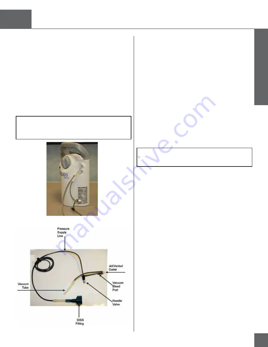
Figure 24:
Jet Venturi assembly
NOTE: The procedure for the H300 can be duplicated on the
H850 if continuous flow is not achieved by blowing into the
cannula.
RP3A – Emptying the Unit (H300)
1. Set the flow control valve to a setting of 4.
2. Remove the DISS barb adaptor from the Jet Venturi
Assembly (B-778210-00).
3. Attach that end of the Jet Venturi to the top cannula barb of
the H300.
4. Attach the opposite end of the Jet Venturi to the bottom
cannula barb of the H300.
5. Open the Jet Venturi needle valve. Ensure that the Jet
Venturi outlet and the bleed port remain open.
CAUTION: Damage to the demand flow control valve is
possible. Make sure you hook up the tube exactly as shown in
Figure 19 and do not block the Jet Venturi outlet or the bleed
port.
Figure 23:
Jet Venturi installation


