background image

18

31-2000815 Rev. 0

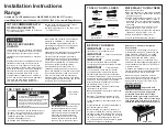
ACCESSORIES—30” TO 36” ADJUSTABLE BACKSPLASH (not included)

UXADBS36PSS, UXADBS48PSS Accessory Installation

■  This backsplash adjusts to fit the space between 

the top of the range and the bottom of the hood, 

from 30” Min. to 36” Max. height.

■  Maximum shelf load-bearing weight is 40 lbs.

TOOLS AND MATERIALS REQUIRED

■  Gloves to protect against sharp edges
■  T-15 and #2 Phillips screwdrivers
■  Drill with 3/32” and 9/64” bits
■  Safety glasses
■  Level
■  Pencil

This Kit Includes 

■  Top wall support 
■  Bottom wall support 
■  Top cover with shelf
■  Bottom cover
■  Hardware package with

  –   9 Stainless Steel Torx 15 #8


self-tapping screws

  –  9 Phillips #2 pan head wood


#10 screws

  –  3 Stainless Steel #2 truss head 


#10 screws (for alternate  

installation method)

INSTALL THE WALL SUPPORT PANELS

WARNING

 The wall support panels must be 

securely fastened to the wall . Failure to do so could 

result in damage or personal injury .

IMPORTANT:

 This backsplash is designed to cover 

the wall between the bottom of the hood and the top of 

the range . The vent hood should be installed over the 

rangetop or range before installing this backsplash .

■  Install and level the Range/Rangetop according to 

the product installation instructions .

■  Remove backsplash packaging and protective film.
■  Locate wall studs on each side. Where studs are not 

available, plan to use wall anchors (not provided).

■  Use a level to pencil 2 horizontal lines on the wall, 

one 1/8” below the vent hood and the other 1/8” 

above the Range/Rangetop. This 1/8” space allows 

the cover panels to overlap the wall supports .

■  Secure the top wall support panel to the wall with 4 

wood screws, through the outermost studs.

■  Use 4 wood screws to secure the bottom wall support 

panel . The center slot should be positioned at the top .

The gap between the top and bottom support panels 

will be covered by the top cover with shelf .

Hardware 

Package

761Dia65

Top Cover 

with Shelf

Bottom Cover

Bottom Wall Support

Top Wall 

Support

1/8”

Secure the 

top panel to 

the wall with 4 

wood screws

1/8”

Secure the 

bottom panel to 

the wall with 4 

wood screws

Wood  

Screws

Center  

Arrow

Wood 

Screws

Summary of Contents for C2Y366

Page 1: ...l Gas From Propane LP 11 Gas Supply 11 Electrical Connections 12 4 Wire Power Cord Installation 12 3 Wire Power Cord Installation 13 Roll Range into Position 13 Level the Range 14 Replace Oven Door s...

Page 2: ...Code ANSI NFPA 70 latest edition In Canada electrical grounding must be in accordance with the current CSA C22 1 Canadian Electrical Code Part 1 and or local codes See Electrical Connections in this...

Page 3: ...e range and carpeting For Caf Parts and Accessories visit our website at cafeappliances com In Canada cafeappliances ca If you received a damaged range you should contact your dealer VENT HOOD COMBINA...

Page 4: ...pliance and behind appliance wall As defined in the National Fuel Gas Code ANSI Z223 1 CSA B149 1 Current Edition Clearances from non combustible materials are not part of the ANSI Z21 1 CSA 1 1 scope...

Page 5: ...in the National Fuel Gas Code ANSI Z223 1 CSA B149 1 Current Edition Clearances from non combustible materials are not part of the ANSI Z21 1 CSA 1 1 scope and are not certified by CSA Clearances les...

Page 6: ...Height 1 As defined in the National Fuel Gas Code ANSI Z223 1 CSA B149 1 Current Edition Clearances from non combustible materials are not part of the ANSI Z21 1 CSA 1 1 scope and are not certified by...

Page 7: ...MATERIALS PROVIDED Oven Rack Lubricant Runners to protect flooring 1 2 Pipe Elbow Anti Tip Bracket Brace and Screws Leveling Leg Wrench Adjustable Wrench 1 4 Driver or Wrench Safety Glasses Drill and...

Page 8: ...n door s and remove packaging Remove shelf holding broiler pan tape literature package shelf lubricant and probe CAUTION Doors and passageways leading to the installation location require at least 32...

Page 9: ...panels place a pad between the hand truck and the range 5 Tilt the range to lower the hand truck wheels off the skid 6 Place the appliance runners on the floor at the left and right sides in front of...

Page 10: ...n the recessed area Install 2 hex screws provided through the brace and into the range NOTE This anti tip device may be installed on the opposite side of the range Measure and mark Dimension A see tab...

Page 11: ...ing restricts movement of the range the use of a CSA International certified flexible metal appliance connector is recommended unless local codes require a hard piped connection If the hard piping met...

Page 12: ...ssociation This appliance must be supplied with the proper voltage and frequency and connected to an individual properly grounded 50 amp for 48 ranges 30 amp for 36 and 30 ranges branch circuit protec...

Page 13: ...nge at the factory Use the following steps to change the range to a 3 wire cord WARNING The neutral or ground wire of the power cord must be connected to the neutral terminal located in the center of...

Page 14: ...t the legs and allow the range to rest on its rollers Be sure to return the wrench to its storage slot for future use 10 LEVEL THE RANGE cont REAR LEG ADJUSTMENT WARNING To reduce the risk of fire or...

Page 15: ...ft in the off position Make sure the flow of combustion and ventilation air to the range is unobstructed Check that all packing materials and tape have been removed This will include tape on metal pan...

Page 16: ...ge Loosen the two screws on each end Adjust the toekick height by sliding the upper and lower pieces apart to 1 8 less than the measured height Secure the top and bottom sections by tightening the 2 s...

Page 17: ...getop and the range hood according to the installation instructions Remove the backsplash packaging and protective film Use a level to pencil a horizontal line on the wall 1 8 above the range or range...

Page 18: ...the wall between the bottom of the hood and the top of the range The vent hood should be installed over the rangetop or range before installing this backsplash Install and level the Range Rangetop ac...

Page 19: ...s blocked Install bottom cover over the bottom support while driving one screw into each side Hold top cover in place while marking screw locations just below shelf support and onto bottom cover Remov...

Page 20: ...allations described in this book safety glasses or goggles should be worn NOTE Product improvement is a continuing endeavor at GE Appliances Therefore materials appearance and specifications are subje...

Reviews: