


FAST-PS-M – User’s Manual
31
is subtracted from the total voltage available at the output. Follow the instructions below
to configure the power supply for remote sensing:
1.
Ensure that Mains switch is on Off position “O”
2.
Remove factory jumpers between
+S
to
+
and
–S
to
–.
3.
Using a twisted pair or shielded cable (suggested wire size is 0.3 or 0.5
mm
2
) connect the
+S
terminal to the positive output terminal and the
–S
to the negative output terminal as illustrated in
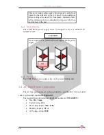
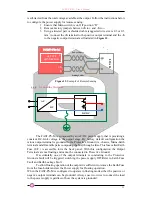
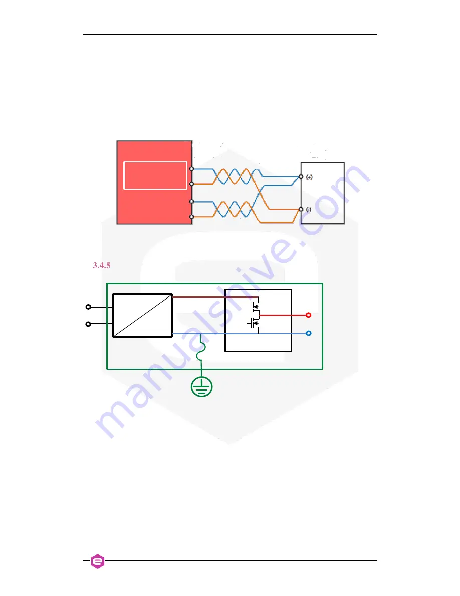
Figure 15.
Figure 15
: Example of Remote Sensing
Grounding Outputs
The FAST-PS-M is composed by an AC/DC power supply that is providing a
constant DC-Link voltage to the output stage. By factory default configuration the
minus output terminal is grounded to the Protective Ground (i.e. chassis, Mains-Earth
terminal and all metallic parts composing the box) through a fuse. This fuse called Earth
Fuse (E.F.) is accessible form the back panel. With this configuration the Output
Terminals are not floating and cannot be connected to Protective Ground.
If accidentally one of the output terminals is conducting to the Protective
Ground a fault will be triggered switching the power supply Off. Refer to Earth Fuse
Fault and Earth Leakage Fault.
To allow floating operation of the output it is sufficient to remove the Earth Fuse
from the fuse-holder and set the Power supply for Floating operation.
When the FAST-PS-M is configured to operate in floating mode either the positive or
negative output terminals can be grounded. Always use two wires to connect the load
to the power supply regardless of how the system is grounded.
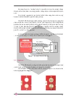
FAST-PS-M
LOAD
+S
-S
+
-
Power Cables
Sensing Cables
OUTPUT
CONNECTOR
AC
DC
DC/DC