


FAST-PS-M – User’s Manual
17
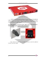
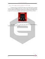
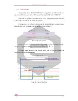
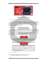
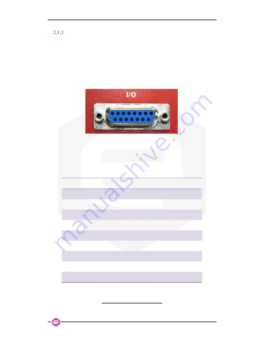
I/O Connectors
The FAST-PS-M module has two configurable dry-contact input interlocks and
output status signals that are directly available on the D-Sub 15 Pin Female connector
on the rear panel (
Figure 5
).
A mating connector, a standard D-Sub 15 Pin Male type, can be installed in
order to use/access these available signals.
Figure 5:
I/O Connector
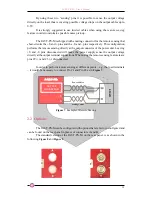
The pin index of the D-Sub 15 rear connector is summarized in the following
table:
Pin Number
Signal name
#1 - #4
DNC
#5
Magnetic Relay Common Contact (C-TAP)
#6
Magnetic Relay Normally Closed Contact (NC-TAP)
#7
Interlock #2 input
#8
Interlock #1 return
#9 - #12
DNC
#13
Magnetic Relay Normally Open Contact (NO-TAP)
#14
Interlock #2 return
#15
Interlock #1 input
Table 2:
D-sub 15 Pin pinout
DNC = DO NOT CONNECT
Pin #1
Pin #8
Pin #9
Pin #15