4
8.
From inside the building, feed the end of the 30-foot
conduit (INCLUDED and pre-wired from transfer switch)
through the wall to the outside.
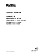
9.
Remove the threaded lock nut from the conduit coupling.
10.
Lift cover. Remove internal
cover plate screw and internal
cover. Remove the knock out
in the lower right corner of the
external connection box. From
the rear of the connection box,
feed wires, 4-pin and 2-pin plugs
into box. Slip the lock nut over
wires and plugs and tighten
securely onto conduit coupling.
Using appropriate fasteners,
mount external connection box
over pre-drilled hole to fully con-
ceal the hole. Seal around the hole and conduit with silicone
caulk from both the inside and outside of the building. Also,
caulk around the sides and top of the box to seal the edges
to the siding or wall. Connect wires to lugs; black to black,
white to white, and red to red. Torque nuts to 20 in/lbs. Snap
together the 4-pin and 2-pin plug connector. Loosen nut from
grounding lug and attach ground wire (green) from conduit.
Reinstall nut and tighten to 45 in/lbs. Reinstall internal cover
plate and screw. Close cover and install lock. This wiring is
complete.
The outdoor connection box must be locked to
ensure safety and to discourage tampering.
11.
Locate automatic transfer switch with built-in emergency
load center in close proximity to the main distribution
panel. The transfer switch can be located to the left or
right of the main distribution panel. Two (2) feet is the
suggested distance (see Figure 11). The transfer switch
may be located a different distance from the main panel
depending on available mounting area. Using the two
(2) foot conduit connected straight across to the main
panel is another option. Always adhere to local electrical
codes during installation. Hold transfer switch against
the mounting surface. Level the transfer switch and mark
the mounting holes. Drill the appropriate size pilot holes.
Mount transfer switch with built-in load center to mounting
surface with appropriate fasteners.
The manufacturer recommends that a licensed elec-
trician or an individual with complete knowledge of
electricity perform the procedures in Sections 12 and
13.
Switch service main circuit breaker to the
OFF (OPEN) position prior to removal of
cover or removal of any wiring of the main
electrical distribution panel. The wires con-
nected to the service main circuit breaker
remain LIVE or HOT. Avoid contact with these wires and
the service main circuit breaker connection lugs.
10
Feed Conduit and Wires
8
Silicone
Caulk
The outer diameter of the conduit
connector is 1-11/16”
Threaded Lock Nut
9
The outer diameter of the threaded
end is 15/16 inches.
Mounting Automatic Transfer Switch
11
Two (2)
Feet
Suggested
Distance
OFF
Residential Transfer Switch Installation Guide
Summary of Contents for 8kW
Page 1: ...Study Guide S e r v i c e T r a i n i n g Air Cooled Training...
Page 2: ......
Page 36: ...32 32 Section 7 Notes Air cooled Generators...
Page 37: ...33 Section 8 Installation Diagrams Air cooled Generators Circuit Breakers Drawing No 0G8573 A...
Page 38: ...34 Section 8 Installation Diagrams Air cooled Generators Generator Drawing No 0G8280 D...
Page 39: ...35 Section 8 Installation Diagrams Air cooled Generators Generator Drawing No 0G8280 D...
Page 42: ...Part No 0G8334 Revision D 09 16 08 Printed in U S A Catalog No OMASPCA S 01...
Page 58: ...14 Section 5 Electrical Data RTSS Type Transfer Switch Wiring Diagram Drawing No 0G7817 B...
Page 59: ...15 Section 5 Electrical Data RTSS Type Transfer Switch Wiring Diagram Drawing No 0G7817 B...
Page 64: ...20 Section 7 Notes...
Page 65: ...21 Section 7 Notes...
Page 66: ...Part No 0G8637 Revision D 08 27 08 Catalog No KGALT 1SI Printed in U S A...
Page 68: ......
Page 76: ...8 Residential Transfer Switch Installation Guide Installation Drawing 0H0258 A...
Page 77: ...9 Residential Transfer Switch Installation Guide Installation Drawing 0H0258 A...
Page 78: ...Residential Transfer Switch Installation Guide Installation Drawing 0G8573 A 10 10...
Page 79: ...11 Residential Transfer Switch Installation Guide Electrical Schematic Drawing 0G7959 A...
Page 80: ...12 Residential Transfer Switch Installation Guide Wiring Diagram Drawing 0G7958 A...
Page 81: ...13 Residential Transfer Switch Installation Guide Wiring Diagram Drawing 0G7958 A...
Page 82: ...14 Residential Transfer Switch Installation Guide Load Center Exploded View Drawing 0G8786 C...
Page 84: ...16 Residential Transfer Switch Installation Guide Notes...
Page 85: ...17 Residential Transfer Switch Installation Guide Notes...
Page 86: ...Part No 0G8571 Revision D 07 31 08 Catalog No KGATX100 1SI Printed in U S A...
Page 91: ...5 REFERENCE Items supplied in the EZ Transfer operator kit...
Page 92: ...6...
Page 93: ...7...
Page 95: ...Air cooled Generator Battery Charger Installation Guidelines...
Page 113: ...17 Section 6 Notes Battery Charger Installation Guidelines...
Page 114: ...Part No 0G7956 Revision B 11 14 08 Printed in U S A...
Page 115: ......