


Front and Rear Panel Descriptions
80-10200000-01 3–9
1. Only connect apparatus complying with the requirements of
SELV in accordance with clause 2-3 of EN 60 950 to the ports
on the rear panel of your unit marked “User, Link, 10 Base-T
and Command”.
An die Anschluesse “User, Link, 10BaseT, und Command”
auf der Rueckseite des Geraetes duerfen nur Komponenten,
die fuer SELV bestimmt sind und der Vorschrift EN 60950/2-3
genuegen, angeschlossen werden.
2. Only connect apparatus complying with the requirements of
TNV 1 in accordance with clause 6 of EN 60 950 to the port
on the rear panel of your unit marked “ISDN BRI”.
An den Anschluess “ISDN BRI” auf der Rueckseite des
Geraetes duerfen nur Komponenten, die fuer TNV-1
bestimmt sind und der Vorschrift EN 60950/6 genuegen,
angeschlossen werden.
3.4 Supply Ratings
WARNING:
1. The unit should be professionally installed by a competent
engineer. There are no operator serviceable parts inside
the unit and it should only be opened by a qualified service
engineer. The mains supply should be disconnected before
accessing the interior.
Gefäh! Bereich. Nur für fachpersonal. Nicht öffnen
berührungsgefahr!
The unit can be connected to supplies of the following voltage ranges:-
a) 100 to 120VAC Nominal (Tolerance Range of 90 to 132VAC)
b) 220 to 240VAC Nominal (Tolerance Range of 198 to 254VAC)
Supply frequencies, in all cases, can be in the range 48Hz to 62Hz.
Summary of Contents for SmartSwitch SBU128
Page 3: ...SBU128 User Manual 80 10200000 01 iii History Sheet 80 10200000 01 V1 00 Software 31 July 1998...
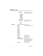
Page 74: ...SBU128 User Manual 80 10200000 01 11 2 11 1 Configuration Menu...
Page 75: ...Command Maps 80 10200000 01 11 3...
Page 76: ...SBU128 User Manual 80 10200000 01 11 4 11 2 Operation Menu...


