background image

7X

8X

9X

10X

11X

12X

1X

2X

3X

4X

5X

6X

ESX-1320

COM 2

COM 1

DISPLAY

RESET

MULTI PORT ETHERNET SWITCH

WITH 

FDSE™

AND 

LANVIEW®

PWR

CPU

RECEIVE

TRANSMIT

PORT

1

2

3

4

5

6

7

8

9 10 11 12

BRIM-A100

STY

LNK

XMT

RCV

ESX-1380

COM 2

COM 1

DISPLAY

RESET

MULTI PORT ETHERNET SWITCH

WITH 

FDSE™

AND 

LANVIEW®

PWR

CPU

RECEIVE

TRANSMIT

PORT

1

2

3

4

5

6

7

8

9 10 11 12

BRIM-A100

STY

LNK

XMT

RCV

PORT 12

TX

RX

PORT 11

TX

RX

PORT 10

TX

RX

PORT 9

TX

RX

PORT 8

TX

RX

PORT 7

TX

RX

PORT 6

TX

RX

PORT 5

TX

RX

PORT 4

TX

RX

PORT 3

TX

RX

PORT 2

TX

RX

PORT 1

TX

RX


ESX-1320/ESX-1380

INSTALLATION GUIDE

Summary of Contents for ESX-1320

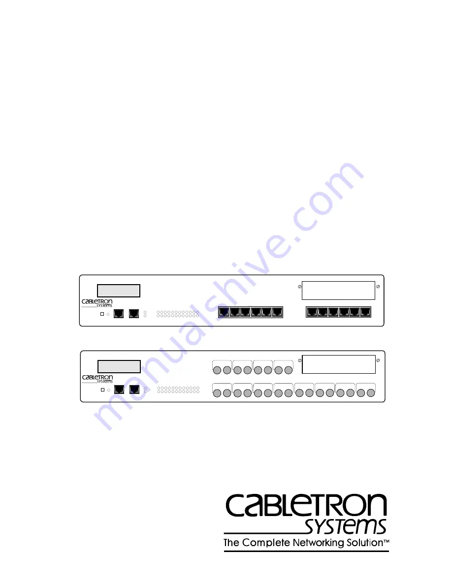
Page 1: ...M A100 STY LNK XMT RCV ESX 1380 COM 2 COM 1 DISPLAY RESET MULTI PORT ETHERNET SWITCH WITH FDSE AND LANVIEW PWR CPU RECEIVE TRANSMIT PORT 1 2 3 4 5 6 7 8 9 10 11 12 BRIM A100 STY LNK XMT RCV PORT 12 TX RX PORT 11 TX RX PORT 10 TX RX PORT 9 TX RX PORT 8 TX RX PORT 7 TX RX PORT 6 TX RX PORT 5 TX RX PORT 4 TX RX PORT 3 TX RX PORT 2 TX RX PORT 1 TX RX ESX 1320 ESX 1380 INSTALLATION GUIDE ...

Page 2: ......

Page 3: ... Cabletron Systems Inc All other product names mentioned in this manual may be trademarks or registered trademarks of their respective companies FCC NOTICE This device complies with Part 15 of the FCC rules Operation is subject to the following two conditions 1 this device may not cause harmful interference and 2 this device must accept any interference received including interference that may cau...

Page 4: ...t preventing radio interference in commercial and or industrial areas Consequently when used in a residential area or in an adjacent area thereto radio interference may be caused to radios and TV receivers etc Read the instructions for correct handling CABLETRON SYSTEMS INC PROGRAM LICENSE AGREEMENT IMPORTANT Before utilizing this product carefully read this License Agreement This document is an a...

Page 5: ... DAMAGES IN NO EVENT SHALL CABLETRON OR ITS SUPPLIERS BE LIABLE FOR ANY DAMAGES WHATSOEVER INCLUDING WITHOUT LIMITATION DAMAGES FOR LOSS OF BUSINESS PROFITS BUSINESS INTERRUPTION LOSS OF BUSINESS INFORMATION SPECIAL INCIDENTAL CONSEQUENTIAL OR RELIANCE DAMAGES OR OTHER LOSS ARISING OUT OF THE USE OR INABILITY TO USE THIS CABLETRON PRODUCT EVEN IF CABLETRON HAS BEEN ADVISED OF THE POSSIBILITY OF SU...

Page 6: ...C EN 55022 EN 50082 1 EN 60950 Equipment Type Environment Networking Equipment for use in a Commercial or Light Industrial Environment We the undersigned hereby declare under our sole responsibility that the equipment packaged with this notice conforms to the above directives Manufacturer Legal Representative in Europe Mr Ronald Fotino Mr J Solari ___________________________________ ______________...

Page 7: ...PTER 3 INSTALLATION 3 1 Unpacking the ESX 3 2 3 2 Removing the Chassis Cover 3 3 3 3 Setting Mode Switches 3 5 3 4 NVRAM Reset Switch 3 8 3 5 SIMM Upgrades 3 9 3 5 1 Locating SIMMs 3 9 3 5 2 Installing SIMMs 3 9 3 6 BRIM Connection 3 12 3 7 Installing the ESX 3 12 3 7 1 Tabletop or Shelf Installation 3 13 3 7 2 Rackmount Installation 3 14 3 7 3 Connecting to the Power Source 3 16 3 8 Pre Network I...

Page 8: ...ges 4 9 4 4 3 Alarm Messages 4 11 4 4 4 Saved System Messages 4 12 4 4 5 Failure or Error Messages 4 14 APPENDIX A SPECIFICATIONS A 1 Functionality A 1 A 2 COM Port 1 and COM Port 2 A 1 A 3 Environmental Requirements A 2 A 4 Regulatory A 2 A 5 Physical Properties A 2 A 6 Electrical Specifications A 2 APPENDIX B ETHERNET CABLING REQUIREMENTS B 1 Network Requirements B 1 B 2 10BASE T Twisted Pair Ne...

Page 9: ...ation Figure 1 1 ESX 1320 and ESX 1380 Switches NOTE Throughout this manual the term ESX refers to both switches the ESX 1320 and the ESX 1380 If the information applies to only one of the switches then that switch is referred to by its model name ESX 1320 or ESX 1380 1574 01 7X 8X 9X 10X 11X 12X 1X 2X 3X 4X 5X 6X ESX 1320 COM 2 COM 1 DISPLAY RESET MULTI PORT ETHERNET SWITCH WITH FDSE AND LANVIEW ...

Page 10: ...ions required to unpack the ESX perform pre installation testing install the ESX and connect the ESX to the network Chapter 4 Troubleshooting provides detailed troubleshooting procedures for the ESX Appendix A Specifications contains information on functionality and operating specifications connector pinouts environmental requirements and physical properties Appendix B Ethernet Cabling Requirement...

Page 11: ... currently supported by the ESX Memory The ESX has 4 Megabytes MB of Shared Dynamic Random Access Memory SDRAM 4 MB of Local Dynamic Random Access Memory LDRAM and 2 MB of FLASH Electrically Erasable Programmable Read Only Memory FLASH EEPROM A new firmware image can also be loaded while the system is operating through a Runtime Download This option allows the loading of a new firmware image from ...

Page 12: ... overall reliability of the network and protect against loop conditions The ESX supports a wide variety of industry standard MIBs including RFC 1213 MIB II RFC 1757 RMON and RFC 1493 Bridge MIB A full suite of Cabletron Systems Enterprise MIBs provide a wide array of statistical information to enhance troubleshooting LANVIEW Diagnostic LEDs The LANVIEW diagnostic and status monitoring LEDs serve a...

Page 13: ...itional support related to this device or if you have any questions comments or suggestions concerning this manual contact Cabletron Systems Technical Support NOTE Note symbol Calls the reader s attention to any item of information that may be of special importance TIP Tip symbol Conveys helpful hints concerning procedures or actions CAUTION Caution symbol Contains information essential to avoid d...

Page 14: ...le type etc Network load and frame size at the time of trouble if known The serial and revision numbers of all Cabletron Systems products in the network The device history i e have you returned the device before is this a recurring problem etc Any previous Return Material Authorization RMA numbers FTP ctron com 134 141 197 25 Login anonymous Password your email address BBS 603 335 3358 Modem setti...

Page 15: ...SET BUTTON The front panel of the ESX has a RESET button that allows you to re initialize the processor Chapter 4 provides procedures for using the RESET button 1574 01 7X 8X 9X 10X 11X 12X 1X 2X 3X 4X 5X 6X ESX 1320 COM 2 COM 1 DISPLAY RESET MULTI PORT ETHERNET SWITCH WITH FDSE AND LANVIEW PWR CPU RECEIVE TRANSMIT PORT 1 2 3 4 5 6 7 8 9 10 11 12 BRIM A100 STY LNK XMT RCV ESX 1380 COM 2 COM 1 DISP...

Page 16: ...ron Systems Remote SPECTRUM Portable Management Applications Third Party SNMP compliant Network Management Packages Network management capabilities provide the necessary management tools for the ESX to operate at full capacity Your ability to set up parameters with network management ensures optimal performance of the ESX Refer to the applicable network management package user s manual for more in...

Page 17: ... Local Management Main Menu screen The MIBNav prompt appears 3 Enter the following commands shown in bold type at the MIBNav prompt as shown below MIBNav ctron MIBNav cd 4 3 3 2 1 1 MIBNav set 5 x y where x equals the port number 1 through 12 where y can equal either 2 for simplex mode or 3 for full duplex mode For example set 5 3 3 would set port 3 for full duplex operation For more information c...

Page 18: ...Chapter 2 Controls and Indicators 2 4 ESX 1320 ESX 1380 Installation Guide ...

Page 19: ...switches Section 3 3 Using the NVRAM reset switch Section 3 4 Adding replacing Single In line Memory Modules SIMMs Section 3 5 Identifying the BRIM connector location Section 3 6 Installing the ESX on a shelf or into a standard rack Section 3 7 Pre network installation testing Section 3 8 Connecting to a network Section 3 9 Only qualified personnel should perform installation procedures NOTE For i...

Page 20: ...mages 2 Grounding strap RJ45 Adapter Kit Release Notes Rack Mounting Kit Accessory Kit ESX 1320 ESX 1380 Installation Guide ESX 1320 ESX 1380 Local Management Guide 3 If any of these items are missing contact Cabletron Systems Technical Support immediately For help refer to Section 1 5 4 Carefully remove the ESX from the shipping box 5 Visually inspect the ESX If there are any signs of damage cont...

Page 21: ...nded for ease of reinstallation c Disconnect all network cables attached to the ESX 2 If the ESX is mounted in a rack perform the following steps Otherwise continue with step 3 Do not remove the cover from the ESX when power is applied to the unit Hazardous voltages are present While performing this procedure remove only the screws shown to remove the cover CAUTION The internal components and boar...

Page 22: ...o the side of the ESX and remove the brackets from the ESX Figure 3 2 Removing the Mounting Brackets Screws 4 19 Inch Rack 7X 8X 9X 10X 11X 12X 1X 2X 3X 4X 5X 6X ESX 1320 COM 2 COM 1 DISPLAY RESET MULTI PORT ETHERNET SWITCH WITH FDSE AND LANVIEW PWR CPU RECEIVE TRANSMIT PORT 1 2 3 4 5 6 7 8 9 10 11 12 1574 05 Screws 4 Rack Mounting Brackets 2 1574 06 1X 2X 3X 4X 5X 6X ESX 1320 COM 2 COM 1 DISPLAY ...

Page 23: ...he chassis cover perform the removal procedures in reverse order 3 3 SETTING MODE SWITCHES Figure 3 4 shows the location and positions of the mode switches These switches are shipped in the positions shown and need not be checked before operating the ESX Never adjust switch settings while the ESX has power applied to it Not only is this dangerous but the change in position activates the switch fun...

Page 24: ... 6 ESX 1320 ESX 1380 Installation Guide Figure 3 4 ESX Mode Switch Location Component Layout ESX Front Panel ESX TOP VIEW WITHOUT COVER LDRAM SDRAM BRIM NVRAM RESET Switch FLASH Mode Switch Bank 1 2 3 4 5 6 7 8 OFF ON 15741 08 ...

Page 25: ...equests a new image download until it either receives a new image from the BOOTP server or the RESET button on the front panel is pressed When the RESET button is pressed the ESX continues trying to contact a BOOTP server but will timeout in approximately one minute If the ESX times out the image is loaded from its FLASH memory Switch 7 Cabletron Systems use only Switch 8 Password Defaults Changin...

Page 26: ...nging the NVRAM reset switch position has no effect on operation until the RESET button is pressed or the power to the ESX is cycled This will initiate the ESX processor and clear the NVRAM of user entered parameters such as IP addresses and community names To change the NVRAM reset switch position use a non metallic tool to reach in through the chassis grillwork and move the switch There is no ne...

Page 27: ...ecific SIMM slot location on the ESX motherboard When installing SIMM boards make sure that you place them in their proper slots Figure 3 4 shows the location of the ESX SIMM slots 3 5 2 Installing SIMMs The ESX has two SIMM slot types FLASH SIMMs use an angle down slot where the SIMM rotates down to a horizontal locked position SDRAM and LDRAM SIMMs use an angle up slot where the SIMM rotates up ...

Page 28: ...slot 4 Pivot the SIMM down until it locks into the clips in the SIMM slot and the SIMM holes fit over the SIMM slot posts Figure 3 6 Installing a FLASH SIMM CAUTION The internal components and boards associated with the ESX are static sensitive devices Use the antistatic wrist band and observe standard antistatic safety procedures when the cover is removed Failure to do so could cause damage or se...

Page 29: ... 4 Pivot the SIMM back until it locks into the clips in the SIMM slot and the SIMM holes fit over the SIMM slot posts See Figure 3 7 Figure 3 7 Installing an SDRAM or LDRAM SIMM CAUTION The internal components and boards associated with the ESX are static sensitive devices Use the antistatic wrist band and observe standard antistatic safety procedures when the cover is removed Failure to do so cou...

Page 30: ...ormation Figure 3 8 BRIM Connector Location 3 7 INSTALLING THE ESX The ESX may be installed on a tabletop shelf or in a 19 inch rack Refer to Section 3 7 1 for information concerning a tabletop or shelf installation Section 3 7 2 describes the rackmount installation To prevent possible personal injury and or damage to the unit do NOT connect power to the ESX until instructed to do so ESX Front Pan...

Page 31: ...t for each ESX Maintain a temperature of between 5 C 41 F and 40 C 104 F at the installation site with fluctuations of less than 10 C per hour Installation For a tabletop or shelf installation locate the ESX within seven feet of its power source and with an unrestricted free surface area as shown in Figure 3 9 Proceed to Section 3 7 3 for power connection instructions Figure 3 9 Tabletop or Shelf ...

Page 32: ...n 5 C 41 F and 40 C 104 F at the installation site with fluctuations of less than 10 C per hour In order to allow for proper cooling there must be a two inch clearance on either side and the back of the unit Installation Rack mounting the ESX involves the following Attaching the strain relief bracket Rack mounting the ESX attaching the mounting brackets and fastening the ESX to the rack Attaching ...

Page 33: ... end of the ESX as shown in Figure 3 11 Figure 3 11 Installing the Rack Mounting Brackets NOTE Do not remove the cover from the ESX Complete any BRIM installation or SIMM upgrades before installing the ESX in a rack Screws 4 Strain Relief Bracket 1574 12 7X 8X 9X 10X 11X 12X 1X 2X 3X 4X 5X 6X ESX 1320 COM 2 COM 1 DISPLAY RESET MULTI PORT ETHERNET SWITCH WITH FDSE AND LANVIEW PWR CPU RECEIVE TRANSM...

Page 34: ... of the supplied power cord into the 3 prong receptacle on the back panel of the ESX 2 Plug the power cord into a grounded wall outlet The POWER LED turns ON green and the CPU LED turns ON green briefly NOTE The ESX has a universal power supply This allows connection of the ESX to power sources ranging from 100 to 125 Vac or 200 to 250 Vac 50 60 Hz NOTE While booting the ESX displays boot diagnost...

Page 35: ...n contact Cabletron Systems for assistance Refer to Chapter 1 Getting Help 3 8 PRE NETWORK INSTALLATION TEST Before connecting the ESX to a live network you may want to test the ESX in a controlled situation to ensure that it is switching packets You can perform this test using two workstations and an ESX To perform this test refer to Figure 3 13 and proceed as follows 1 Install and power up the E...

Page 36: ...ify the proper operation of the ESX If a failure occurs contact Cabletron Systems Technical Support Refer to Chapter 1 Getting Help Figure 3 13 Pre Installation Test NOTE Interface 13 the BRIM requires additional network equipment for proper testing 1574 13 Move Between Ports Client Workstation 7X 8X 9X 10X 11X 12X 1X 2X 3X 4X 5X 6X ESX 1320 COM 2 COM 1 DISPLAY RESET MULTI PORT ETHERNET SWITCH WIT...

Page 37: ...e ESX 1320 to the network proceed to Section 3 9 1 To connect the ESX 1380 to a network proceed to Section 3 9 2 3 9 1 Connecting a Twisted Pair Segment to the ESX 1320 Before connecting a segment to the ESX 1320 check each end of the segment to verify wire crossover To connect a twisted pair segment to the ESX 1320 proceed as follows 1 Refer to Figure 3 14 Connect the twisted pair segment to the ...

Page 38: ...E T device at the other end of the twisted pair segment is ON b Verify that the RJ45 connectors on the twisted pair segment have the proper pinouts Figure 3 15 and check the cable for continuity c Check that the twisted pair connection meets the dB loss and cable specifications outlined in Appendix B If a link is not established contact Cabletron Systems Technical Support Refer to Chapter 1 Gettin...

Page 39: ...iber optic cables to indicate receive and transmit ends Many cables are prelabeled providing matching labels or tapes at both ends of each strand of cable 1 Remove the protective plastic covers from the fiber optic ports on the applicable port on the module and from the ends of the connectors on each fiber strand CAUTION Do not touch the ends of the fiber optic strands and do not let the ends come...

Page 40: ... ports of the other device being connected If link indicators are present for the fiber optic connection check that they are ON If an indicator is present but not ON that port does not have a valid link Perform each of the following steps until you reach a resolution of the problem and achieve a link Check that the device at the other end of the link is ON Verify proper crossover of the fiber stra...

Page 41: ... 4 1 USING LANVIEW The ESX uses the Cabletron Systems built in visual diagnostic and status monitoring system called LANVIEW With LANVIEW you can quickly scan the LANVIEW LEDs Figure 4 1 of the ESX to observe network status or diagnose network problems Refer to Table 4 1 for a description of the LEDs Figure 4 1 LANVIEW LEDs ESX 1320 COM 2 COM 1 DISPLAY RESET MULTI PORT ETHERNET SWITCH WITH FDSE AN...

Page 42: ...ise press the RESET button Yellow Testing Board performing memory test Verify LED blinks green after approx 180 seconds Otherwise press the RESET button Transmit Off Port enabled no activity Should flash green every 2 seconds indicating BPDUs being sent if Spanning Tree Algorithm is active Green Flashing Indicates activity or enabled port Note that the flashing is pulsed stretched for easy viewing...

Page 43: ...Solid Port enabled link no activity No error Yellow Flashing Indicates receive activity No error Red Solid No link port disabled Blinking Link but port disabled Contact Cabletron Systems Technical Support for assistance Table 4 1 LANVIEW LEDs Continued LED Color Description Error Condition Recommended Action ...

Page 44: ...stalled Check the proper connection of the power cable and its access to a live outlet No Local Management Password screen Terminal setup is not correct Improper console cable UPS cable pinouts Refer to ESX Local Management Guide for proper setup procedures Refer to ESX Local Management Guide for proper console port pinouts Cannot contact the ESX from in band management Improper Community Name Tab...

Page 45: ... your network User parameters IP address Device and Module name etc are lost when the ESX is powered down or the front panel RESET button is pressed Position of the NVRAM Reset Switch was changed before the last power down or pressing of the RESET button causing the user entered parameters to reset to factory default settings NVRAM may be defective Reenter the lost parameters as necessary Call Cab...

Page 46: ...n use a pen or pencil to press and release the button The ESX goes through an initialization process for approximately 180 seconds NOTE The RESET button may be used in conjunction with the NVRAM reset switch not shown to also initialize the NVRAM as described in Section 3 4 1574 18 RESET Button ESX 1320 COM 2 COM 1 DISPLAY RESET MULTI PORT ETHERNET SWITCH WITH FDSE AND LANVIEW PWR CPU 1 2 3 4 5 6 ...

Page 47: ...ing the DISPLAY button The LCD and the DISPLAY button are shown in Figure 4 3 Figure 4 3 LCD and DISPLAY Button The following five types of messages are displayed on the LCD Initialization Messages Static System Messages Alarm Messages System Messages Failure or Error Messages These messages are displayed as an associated event occurs and are not saved to be displayed later using the DISPLAY butto...

Page 48: ...s are generated during power up and appear as events occur These messages track the boot up sequence They are not saved and cannot be recalled using the DISPLAY button Cabletron Hardware Init Cabletron Boot From Flash Cabletron BOOTP Discovery Cabletron RARP Req State Cabletron TFTP Req State Cabletron TFTP in Progress Cabletron TFTP Complete Cabletron Erasing Flash Cabletron Programming Flash Cab...

Page 49: ...he product name To Exit There are three ways to exit the Static System Messages From the last Static System message Momentarily press the DISPLAY button while the last message COM 2 Port Function xxxxx is displayed The display automatically returns to the product name Automatic 20 second exit Allow 20 seconds to elapse after the last DISPLAY button operation The display returns to the product name...

Page 50: ... Displays the revision number of the FLASH EEPROM Boot PROM Rev xx xx xx Displays the revision number of the internal Boot PROM Flash Programmed xx Times Displays the number of times a new software load to FLASH has occurred COM 1 Port Baud Rate Auto Displays Auto for the Baud Rate for COM 1 Port COM 1 Port Function xxxxx Displays the current function of the COM 1 Port COM 2 Port Baud Rate Auto Di...

Page 51: ...splay Press and hold the DISPLAY button for 3 seconds while a Static System Message is displayed When the button is released the display steps to the saved Alarm Messages described in Table 4 4 Thereafter each time you press the DISPLAY button the next saved message is displayed To Exit There are two ways to exit the Static System Messages Automatic 20 second exit Allowing 20 seconds to elapse aft...

Page 52: ...d Displays the individual link status of ports 1 through 13 Switch Port x Stand By Indicates if a Switch port is in stand by Individually for ports 1 through 13 Switch Port xx On Line Indicates if a Switch port is on line Individually for ports 1 through 13 No Messages in Queue x No Alarm messages TFTP Host xxx xxx xxx xxx TFTP File xxxxxxx hex Last TFTP File xxxxxxx hex Last TFTP Host xxx xxx xxx...

Page 53: ...ages Thereafter each time you press the DISPLAY button the next saved message is displayed From an Alarm Message display Press and hold the DISPLAY button for 3 seconds while an Alarm Message is displayed When released the display steps to one of the saved System Messages Thereafter each time you press the DISPLAY button the next saved message is displayed To Exit There are two ways to exit the Sy...

Page 54: ...aved and cannot be recalled using the DISPLAY button When any of these messages appear call Cabletron Systems Technical Support The failure or error messages are as follows Cabletron Ctrl Reg Err Cabletron BBRAM Failure Cabletron SDRAM Failure Cabletron Modem SCC Failure Cabletron SONIC Failure Cabletron Bit Swap Failure Cabletron Console SCC Error Cabletron LDRAM Failure Cabletron 82C54 Failure ...

Page 55: ...Shared Sonic Memory 4 MB Internal Processor 2 Intel i960s NVRAM 128 kB Ethernet Controller 12 Sonic Controllers CPU Memory 4 MB A 2 COM PORT 1 AND COM PORT 2 COM ports 1 and 2 are standard RJ45 ports with the following pin assignments Pin Signal Name Input Output 1 Transmit Data XMT Output 2 Data Carrier Detect DCD Output 3 Data Set Ready DSR Input 4 Receive Data RCV Input 5 Signal Ground GND NA 6...

Page 56: ...to 90 non condensing A 4 REGULATORY Safety UL 1950 CSA C22 2 No 950 EN 60950 IEC 950 and 73 23 EEC Electromagnetic Compatibility EMC FCC Part 15 VCCI Class 1 EN 55022 EN 50082 1 and 89 336 EEC A 5 PHYSICAL PROPERTIES Dimensions 7 11H x 43 18W x 34 29D cm 2 8H x 17W x 13 5D in Weight Unit 3 18 kg 7 lb A 6 ELECTRICAL SPECIFICATIONS Input 100 125 V 4 0 A 200 250 V 2 0 A Phasing Single phase Frequency...

Page 57: ...ets the following requirements Length The IEEE 802 3 10BASE T standard requires that 10BASE T devices transmit over a 100 meter 328 foot link using 22 24 AWG unshielded twisted pair wire This is supported by Cabletron Systems However cable quality largely determines maximum link length If you use high quality low attenuation cable you can achieve link lengths of up to 200 meters Cable delay limits...

Page 58: ...ks must not generate more than 5 0 ns of jitter Make sure your cable meets 10BASE T link impedance requirements to rule out jitter as a concern Delay The maximum propagation delay of a 10BASE T link segment must not exceed 1000 ns This 1000 ns maximum delay limits the maximum link segment length to no greater than 200 meters Crosstalk Signal coupling between different cable pairs within a multi pa...

Page 59: ...Delay When you determine the maximum fiber optic cable length to incorporate fiber runs into your network you must calculate and consider the fiber optic budget a total loss of 10 0 dB or less is permissible between stations and total network propagation delay To determine the fiber optic budget combine the optical loss due to the fiber optic cable in line splices and fiber optic connectors Typica...

Page 60: ...Appendix B Ethernet Cabling Requirements B 4 ESX 1320 ESX 1380 Installation Guide ...

Page 61: ...1320 1 3 ESX 1380 1 3 Controls and indicators location of 2 1 Crosstalk B 2 E Electrical specifications A 2 Electromagnetic Compatibility A 2 Environmental requirements A 2 ESX functionality A 1 installation of 3 12 management 1 4 memory 1 3 specifications A 1 unpacking 3 2 ESX 1320 connection See connectivity ESX 1380 connection See connectivity F Features See ESX Fiber optics See 10BASE F FLASH ...

Page 62: ... 10BASE F multimode B 3 10BASE T B 1 M Management in band 1 4 out of band 1 4 Memory description of 1 3 Mode switches description of 3 5 location of 3 6 positions of 3 7 N Network connecting to 3 19 Network management capabilities of 2 2 NVRAM reset switch location of 3 8 use of 3 8 O Out of band management 1 4 P Physical properties A 2 Port configuration for full duplex 2 3 for simplex 2 3 Power ...

Page 63: ...M upgrades description of 3 9 Simplex mode configuration of 2 2 Specifications A 1 Switching types supported 1 4 T Tabletop or shelf installation 3 13 Troubleshooting using LANVIEW LEDs for 4 1 using LCD messages for 4 7 using the checklist for 4 4 Twisted pair connection of 3 19 U Unpacking the ESX 3 2 ...

Page 64: ...Index Index 4 ESX 1320 ESX 1380 Installation Guide ...

Page 65: ... Anwendung des Geraetes geeignet und der zum Benuetzen im Lande der Anwendung anerkannt ist SPANISH El cable principal de la red eléctrica utilizado con este equipo debe tener 2 conductores y 1 toma de tierra con un mínimo de 0 75 mm2 cada uno y necesita tener un aparato de acoplamiento standard IEC en un extremo y un enchufe para el cable principal de la red eléctrica en el otro extremo lo cual s...

Page 66: ......

Reviews: