PVC Addendum to the 9A686-04/9A656-04 Configuration Guide
9033126-01
Page 41 of 43
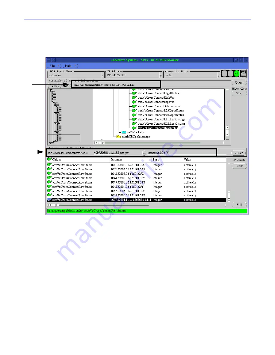
Step 29. Assign the CCID to both sides of the PVC.
This section describes how to assign the CCID, which was learned back in
step 24
, to both sides of the
PVC. Refer to
Figure 30
.
Figure 30 Assigning the CCID to Both Sides of the PVC
Figure 30
contains two callouts, which are described as follows:
A
Displays the MIB command used to view this information (atmVclCrossConnectRowStatus) and the OID
string used to access this command (1.3.6.1.2.1.37.1.11.1.13).
B
Displays the following information that must be entered for the PVC to be activated:
•
CCID (in this example, 4099)
•
Interface of the first side of the PVC (in this example, 30301)
•
VPI of the PVC (in this example, 11)
•
VCI of the PVC (in this example, 113)
•
Interface of the second side of the PVC (in this example, 30302)
A
B


