37
A 3
Wechsel der Kupplung für den Abwickler Transferfolie:
5. Lösen Sie mit einem Innensechkantschlüssel 2 mm die
beiden Gewindestifte (6) der Nabe (5)!
6. Ziehen Sie die Nabe (5) ab und stecken Sie die neue
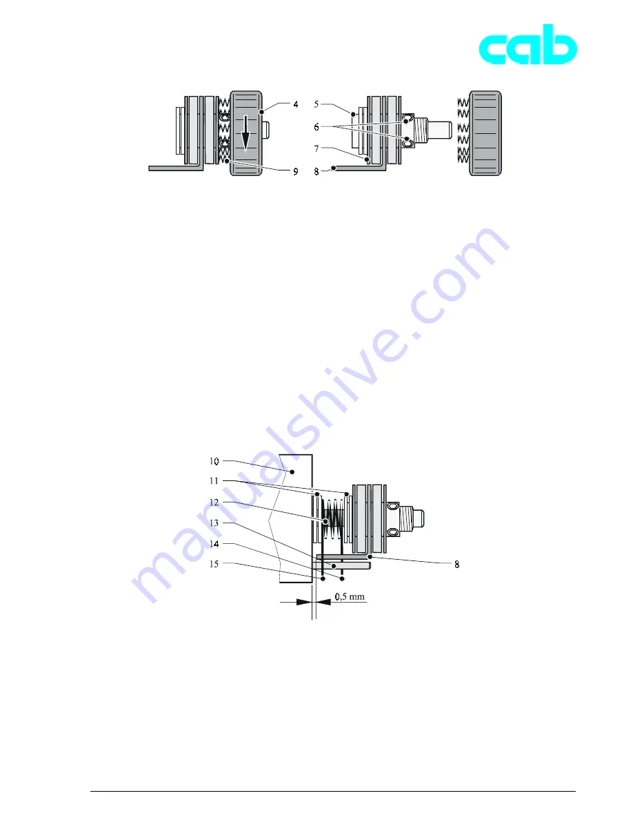
Nabe auf die Achse. Achten Sie beim Aufschieben
darauf, dass der Mitnehmer (8) zwischen die
Federenden (14, 15) geschoben wird.
Auf der Achse befinden sich von der Montagewand
(Gussoberfläche) ausgehend folgende Bauteile:
- Passscheiben (11)
- 1 Feder (12)
- Passscheiben (11) und
- Nabe mit Kupplungsscheiben und Mitnehmer.
Der Stift (13) befindet sich mittig zwischen den beiden
Federenden (14, 15).
7. Ziehen Sie die Gewindestifte (6) an.
8. Geben Sie mit Hand Druck auf die Kupplungsscheiben
und stellen Sie den Abstand zwischen Mitnehmer (8)
und der Gussoberfläche (10) fest. Dieser soll etwa 0,5
mm betragen, anderenfalls muss die Nabe gelöst und
neu positioniert werden.
9. Bei richtigem Abstand: Drehen Sie die Rändelmutter
(4) mit den 6 Federn (9) auf die Nabe (5) bis zum
Anschlag auf (mäßige Handkraft anwenden).
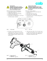
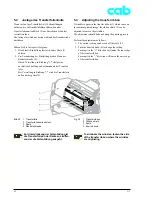
Bild 22
4 Rändelmutter
5 Nabe
6 2 Gewindestifte
7 Kupplungsscheiben
8 Mitnehmer
9 6 Federn
Fig. 22
4 Knurled nut
5 Hub
6 2 Threaded pins
7 Clutch plates
8 Driver
9 6 Springs
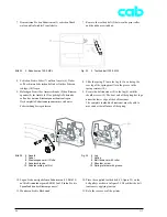
Bild 23
Nabenmontage
Fig. 23
Hub assembly
7. Tighten the threaded pin (6).
8. Apply hand pressure to the clutch plates and set the
distance between the driver (8) and the cast surface
(10). This must be about 0.5 mm, otherwise the hub
must be released and repositioned.
9. With the correct distance, turn the knurled nut (4) with
the 6 springs (9) on the hub (5) as far as it will go
(apply moderate pressure with the hand).
Replacing the clutch for the ribbon supply hub:
5. Loosen the two threaded pins (6) on the hub (5) with
the 2 mm Allen key.
6. Remove the hub (5) and slide the new hub onto the
axle. When sliding the hub on, ensure that the
driver (8) is slid between the ends of the springs (14,
15).
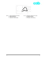
The following components are located on the axle,
starting from the wall (cast surface).
- Shim rings (11)
- 1 Spring (12)
- Shim rings (11) and
- Hub with clutch plates and driver.
The pin (13) is located centrally between the two spring
ends (14, 15).


