34
A 3
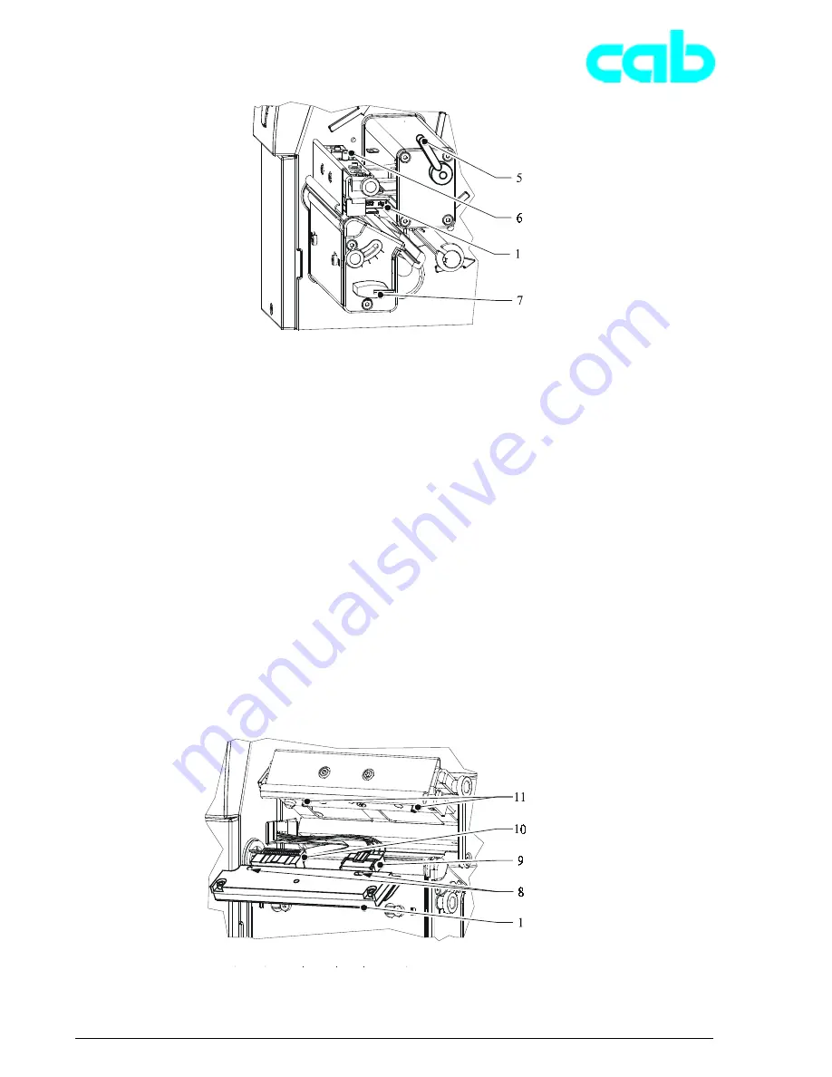
5. Schwenken Sie den Hebel (5, Bild 17) im Uhrzeiger-
sinn bis zum Anschlag und heben Sie dadurch die
Druckkopfbaugruppe an.
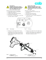
6. Ziehen Sie den Druckkopf (1, Bild 16) von den Stiften
(11) in der Druckkopfhalterung ab.
7. Lösen Sie den Druckkopf (1, Bild 16) von den Steck-
verbindern der beiden Druckkopfkabel (9, 10).
8. Stecken Sie die Kabel am neuen Druckkopf an.
9. Setzen Sie den Druckkopf mit den Bohrungen (8) auf
die Stifte (11) auf.
10. Ziehen Sie die Feststellschraube (6) leicht mit der Hand
an und überprüfen Sie, ob der Druckkopf vollflächig an
der Druckkopfhalterung anliegt.
11. Schwenken Sie den Hebel (5) erneut in die im Bild 17
gezeigte Stellung.
12. Ziehen Sie die Feststellschraube (6) vollständig an,
ohne die Schraube zu überdrehen.
Bild 18
Druckkopf und Steckverbinder
Fig. 18
Printhead and plug connectors
Bild 17
Druckkopf und Feststellschraube
Fig. 17
Printhead and locking screw
5. Swing the lever (5, figure 17) clockwise as far as it will
go and in this way lift the printhead assembly up.
6. Pull the printhead (1, figure 17) off the pins (11) in the
printhead holder.
7. Pull the plugs (9, 10) of both printhead cables out of
the printhead sockets (1, figure 18).
8. Plug the cables into the new printhead.
9. Place the printhead boreholes (8) onto the pins (11).
10. Lightly tighten the locking screw (6) by hand and check
whether the whole of the printhead is lying flat on the
printhead holder.
11. Swing the lever (5) back into the position shown in
figure 17.
12. Completely tighten locking screw (6) without
overtightening it.


