background image

25

8.1 

Test Mode without Print Job

!

Warning!

The pad will immediately be moved in the starting position!

Danger of crushing to hand and fingers by the moving pad! 


Do not reach into the zone of the moving pad and keep long hair, loose clothes, and jewelry distant. 

2

1

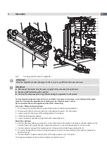
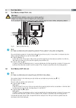
Fig. 19 

Test mode via Enter key

i

Note!


Please use that test mode to adjust the parameter "Peel position" in the printer configuration.

The whole labeling process can be simulated without the need of a print job or a connection to a computer by alter-
nately pressing the 

feed

 (2) key and the Enter key     (1):


Press the 

feed

 key (2). 

A blank label is fed. The vacuum at the pad as well as the supporting air (blow tube) are switched on. After the 
label has been picked up by the pad, the supporting air is switched off. 


Press the Enter key   (1). 
The pad is moved to the labeling position.  A sensor signals when the labeling position is reached. The vacuum is 
switched off and the label is placed onto the product. Then, the pad is moved back into the starting position.

8.2 

Test Mode with Print Job

i

Note!


Please use that test mode to adjust the peel-off offset in the software.

That method allows to check labeling process with the real print data using the Enter key     (1).


Send a print job.

The test mode is executed in two half cycles:


Press the Enter key   (1). 

Half cycle 1


A label is printed. The vacuum at the pad as well as the supporting air (blow tube) are switched on. After the label 
has been picked up by the pad, the supporting air is switched off.


Press the Enter key   (1) again. 

Half cycle 2


The pad is moved to the labeling position.  A sensor signals when the labeling position is reached. The vacuum is 
switched off and the label is placed onto the product. Then, the pad is moved back into the starting position.

If the label is manually removed from the pad after the first half cycle, the half cycle 1 will be repeated when the 

pre-dispense key is pressed again. 

Test Operation

Summary of Contents for 3014

Page 1: ...Service Manual 3014 3016 Made in Germany Front Side Applicator...

Page 2: ...heck www cab de for the latest update Terms and conditions Deliveries and performances are effected under the General conditions of sale of cab Service Manual for the following products Germany cab Pr...

Page 3: ...6 1 Vacuum Adjustments 16 6 2 Blow Tube and Support Air Adjustments 17 6 3 Adjusting the sensors of the swing cylinder 19 6 4 Adjust the speed of the swing cylinder 20 6 5 Adjusting the Product Sensor...

Page 4: ...recognized safety rules However danger to the life and limb of the user or third parties and or damage to the device and other tangible assets can arise during use The device may only be used for its...

Page 5: ...only be performed by trained personnel or service technicians Unauthorized interference with electronic modules or their software can cause malfunctions Other unauthorized work on or modifications to...

Page 6: ...3014 16 L R 3100 3014 16 L R 2100 Label width in mm for Hermes 4 25 114 80 114 25 114 for Hermes 6 25 174 80 174 Label height in mm 25 250 80 250 25 100 Compressed air pressure 0 45 MPa 4 5 bar Sound...

Page 7: ...e applicator to the printer 5 Setting screw to adjust the angle between applicator and printer in X Y layer 6 Setting screw to adjust the angle between applicator and printer in Z X layer 7 Compressed...

Page 8: ...movement 3 Throttle valves speed of the swing cylinder 10 Sensor Product detecting 12 Pad customized 16 Locking Applicator 16 Interface to the printer 17 Valve swing cylinder 18 Valve blow air 19 Val...

Page 9: ...crews included the pad assembly 3 Pad customized 4 Documentation i Note Please keep the original packaging in case the applicator must be returned Attention The device and printing materials will be d...

Page 10: ...backfeed to position the front edge of the next label at the printing line i Note This synchronizing also has to be carried out when the print job has been interrupted with the cancel key Synchronizi...

Page 11: ...n thumbscrew 7 and swing the applicator 2 Disconnect SUB D 15 male connector 8 to the female connector 9 of the printer 3 Loosen screw 6 and move off the locking plate 5 from hinges 4 Lift the control...

Page 12: ...or Process of labeling was braked via the I O interface of the printer with the XSTP signal Refl sensor blk There has been no change of the switch state at the upper sensor at the cylinder between the...

Page 13: ...s ex factory are Connecting on a cab Hermes printer vertical Pressure value of the compressed air 0 45 MPa 4 5 bar 5 2 Tools Screwdriver with parallel blade 2 5 To adjust the throttle valves and produ...

Page 14: ...To secure the applicator against slipping out out of hinges loosen screw 5 and move metal part 4 under the hinges and tighten screw 5 4 Swing the applicator to the printer and tighten the thumbscrew 1...

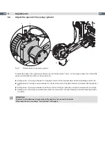
Page 15: ...moving pad and keep long hair loose clothes and jewelry distant 2 1 3 4 1 Check that the stop valve 2 is closed shown in figure 11 2 Attach compressed air at the fitting 1 3 Open the stop valve 2 4 Sw...

Page 16: ...valve vacuum X X Adjust the vacuum on the throttle valve vacuum 1 so that the label will sucked on over the complete area X X To increase the vacuums turn the setting screw on the throttle valve 1 cou...

Page 17: ...e supporting air can be rotated around its axis That way the direction of the supporting air can be optimized 1 Loosen screw 1 2 Put in the blow tube 3 into the tube adapter A 2 Turn the blow tube 3 i...

Page 18: ...er on RP S Tube 2 from valve block to blow tube connector Fitting 3 on the blow tube 2 Activate the valve manually with open compressed air supply and pressing of micro switch 1 to measure the pressur...

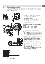
Page 19: ...and labeling process can start Sensor 9 is switched pad is in labeling position The application of the label will start via the product sensor X X Swing the pad assembly in the used position X X Loos...

Page 20: ...t of the pad assembly in direction labeling position B X X Setting screw 1 turning counterclockwise for a faster movement of the pad assembly in direction labeling position B X X Setting screw 2 turni...

Page 21: ...green LED 4 glow Sensor in operation yellow LED 5 glow Sensor is switched A small red light point show the detection point on the product Attention Disconnect the compressed air before the adjustment...

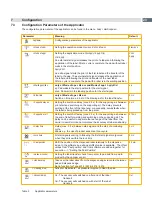
Page 22: ...configuration and the function of the keys in the navigator pad Configuration manual of the printer or Operator s manual of the printer 7 1 Method for Changing the Printer Setup 1 Press menu key 2 Sel...

Page 23: ...lay prevents swirling at the front of the label and consequently avoids faults when the label is being picked up from the printer 0 ms Support del off Setting the switch off delay max 2 5 s for the su...

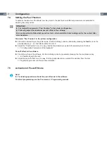
Page 24: ...abeling cycles by alternately pressing the feed key and the pre dispense key 8 1 Test Mode without Print Job X X Adjust the Peel Position in such a way that the blank labels are peeled off completely...

Page 25: ...beling position is reached The vacuum is switched off and the label is placed onto the product Then the pad is moved back into the starting position 8 2 Test Mode with Print Job i Note X X Please use...

Page 26: ...Stamp on Parameters such as mode and waiting position are set automatically Operation Mode Blow Set parameters such as mode and waiting position as follows Mode of appl Apply Print Waiting position up...

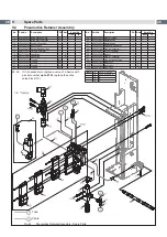
Page 27: ...Screw 1 5 5904544 001 Spring 10 6 5902241 001 Screw DIN7984 M4x10 10 7 1 5970261 001 Mounting Plate 1 A 7 2 5970266 001 Mounting Plate 1 B No Part No Description PU Note Serial No from to 8 5966530 0...

Page 28: ...tor 1 30 5905257 001 Silencer 1 31 5905338 001 Push in T Connector 1 32 5905283 001 Push in threaded Fitting 1 33 1 5964277 001 Blow Tube 2 1 C 33 2 5964095 001 Blow Tube 4 1 D 33 3 5964614 001 Blow T...

Page 29: ...Applicator Control 1 40 5955586 001 Cable 1 41 5971102 001 Cable Retainer 1 No Part No Description PU Note Serial No from to 42 5902571 001 Screw DIN7984 M4x6 10 43 5906943 001 Sealing Ring 1 45 1 595...

Page 30: ...67 Pad customized 1 68 5970263 001 Sensor Product Detecting 1 69 5907249 001 Shock Absorber 1 No Part No Description PU Note Serial No from to 36 1 5979485 001 Sensor 1 F 36 2 5979263 001 Sensor 1 G 3...

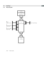
Page 31: ...Applicator Interfaces 46 Sensor Product Detecting CON 2 CON 1 CON 6 CON 3 CON 11 CON 12 19 Valve Block CON 1 39 Applicator Control CON 1 51 Sensor End Position Swing Cylinder 52 Sensor Start Position...

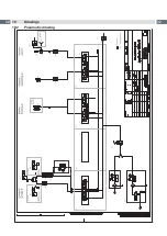
Page 32: ...32 32 10 Drawings Fig 28 Pneumatics 10 2 Pneumatic drawing...

Page 33: ...Labelling Front Side 26 Labelling Rear Side 26 M Mounting 14 O Operation 10 Overview control elements 8 front side 7 rear side 8 P Parameters of the Applicator 23 Peel off Mode 24 Peel Position 24 Pne...

Reviews: