


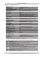


POWER SUPPLY SPECIFICATION
Mains supply 230 Va.c. 50/60 Hz. Max. current 350 mA
Internal Power Supply 27 Vd.c. (nominal)
Total output current limited to 3 A @ 230 Va.c.
Supply and battery charger monitored for failure Yes
Batteries monitored for disconnection and failure Yes
Batteries protected against deep discharge Yes
Max. battery size and type 7 Ah. Use 2 x 12 V VRLA batteries (Part No. BC286/2)
AUXILIARY OUTPUTS
T
ype Open Collector
Max. switching current 25 mA
Max. switching voltage 30 Vd.c.
OP1 Activated when any STANDARD call is active on the system
OP2 Activated when any HELP REQUIRED (ASSIST) call is active on the system
OP3 Activated when any EMERGENCY call is active on the system
OP4 Activated when any ATTACK call is active on the system
OP5 Fault Output. Normal=ON, Fault=OFF.
+24 V Aux. power output 19.5 V minimum, 28 V maximum. Max. current 100 mA. Self-resetting fuse.
FUSES
(to IEC - EN60127 Pt2)
Mains fuse 1 x 1 A HRC ceramic (20 x 5 mm)
Battery fuse 1 x 3.15 A F (20 x 5 mm). This limits the current drawn from the battery.
PANEL INDICATORS AND CONTROLS
Control and menu access buttons Accept (A), Scroll Up, Scroll Down, Code Entry Buttons (1, 2, 3 & 4), Escape (E)
Liquid crystal display (LCD) Two lines x 40 characters, backlit
LED indicator Power Present (LED lit), No Power Present (LED extinguished)
PHYSICAL DIMENSIONS
QT601-2 Quantec Controller 435 (W) x 270 (H) x 85 (D) mm (metal base, plastic lid)
Cutout required for flush mounting using AFP385 bezel 412 (W) x 255 (H) x 50 (D) mm
Flush mount depth 60 mm
Approx. weight (without batteries) 3.5 kg
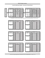
NETWORK CABLING / SPECIFICATION
Connection QT601-2 Quantec Controller to QT603 network splitters
Spine cable 1.5 mm
2
or 2.5 mm
2
(e.g. twin and earth mains cable)
Max. cable length per spine using 1.5 mm
2
150 m
Max. cable length per spine using 2.5 mm
2
250 m
Max. cable length of all spines and limbs 750 m
Limb cable Min 4-core strand security cable, twisted into one pair (to reduce voltage drop)
No. of limbs per splitter 6
Max. cable length per limb 60 m
Max. no of addressable devices per limb 15
Max. no of addressable devices per system 255
Network voltage 24 V (nominal)
Network max. current 3 A
PC/PRINTER/PAGING INTERFACE
QT707S Surveyor PC/Printer connection CONN1 provides RS232 connection using QT600S (or AFP600S) wall socket, connec-
tor lead (supplied with QT707S kit)
QT707 Programming PC connection PL3 provides connection using connector lead (supplied with QT707 software kit)
Pager connection CONN2 provides RS232 connection using QT600S wall socket
OPERATING CONDITIONS
The components are selected to operate within their specification when the environmental conditions outside the enclosure comply with class 3k5
of IEC 721-3-3 : 1978. Temperature range: -5 to +40
o
C. Maximum relative humidity: 95%
PART NUMBERS - QUANTEC CONTROLLER, ENCLOSURES, PROGRAMMING SOFTWARE & INSTALLATION AIDS
QT601-2 Quantec Controller
AFP385 Flush bezel for Quantec Controller
BF359/3S Stainless steel glazed enclosure for Quantec Controller, requires BF359/3CL or BF359/3SL lock kit
BF359/3CL Cam lock kit for BF359/3S
BF359/3SL Electromagnetic solenoid lock kit for BF359/3S
QT707 Quantec upload/download software (Windows 98/2000/XP/VISTA/7 compatible) c/w 4-way molex to 9-way RS232 ‘D’ lead
SAF7070000 4-way molex to 9-way RS232 ‘D’ female programming lead ONLY
BF232 RS232 to USB convertor (allows SAF7070000 to connect to a PC’s USB connector)
QT707S Surveyor Data Management Software, complete with wall socket & lead (Windows 98/2000/XP/VISTA/7 compatible)
QT423 Quantec configurator c/w lead, adaptor & software (Windows 98/2000/XP/VISTA/7 compatible). Used to program special
functions on addressable call points, universal programming devices , hi-output sounders, IR/RF transmitters & pendants.
QT423A Configurator adaptor (allows existing QT423 configurators to program call points)
QT603 Quantec network splitter
BC286/2 24 V 7 Ah VRLA battery pack (2 x 12 V including link wire)
QT601-2 Quantec Controller
Appendix 8 - Technical Specification
Installation & Programming Manual • Approved Document No. DNU6012001 Rev 5 • Page 35 of 42


