


3.0 The Program Menu
3.1 Display Device
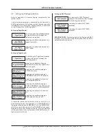
To aid the location of network devices for diagnostic
purposes, it is possible to change the function of the
Controller's LCD display to show the calling device ID number
instead of the place name. Move through the menus to the
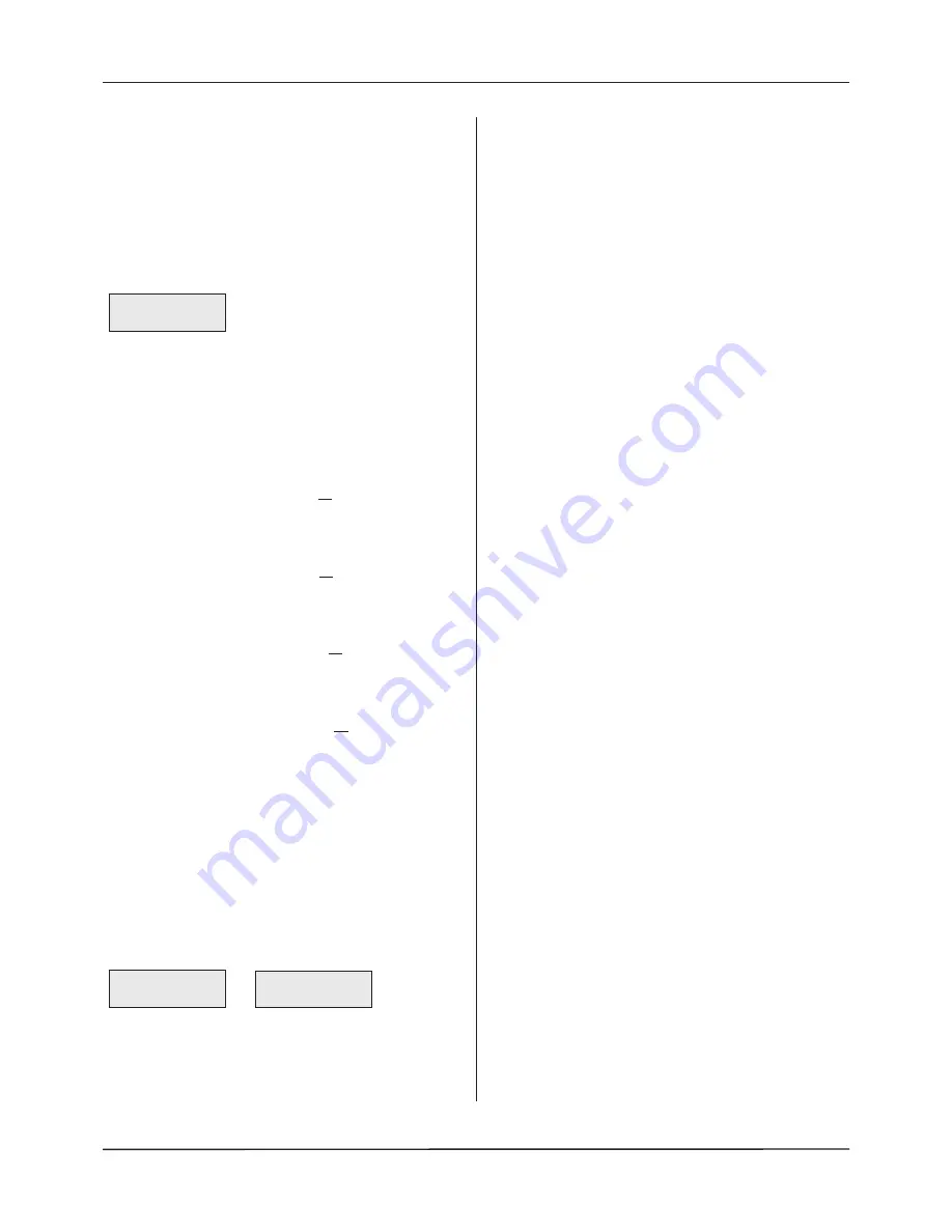
Program Menu and Accept the 'Display Device' prompt. The
following prompt will appear:
When a calling device is activated the ID number of that
device will be shown on the display. (Please note, any other
displays on the system will continue to show the location of
the calling device as normal.) On exiting this function the
network resets itself in order to remove any missed calls from
the Controller.
3.2 Print All
Selecting this function sends a list of all site-specific data to
a printer (if connected).
3.3 Print Devices
Selecting this function sends a list of all network devices to
a printer (if connected).
3.4 Print Groups
Selecting this function sends a list of all Groups (Quantec
Displays) to a printer (if connected).
3.5 Print Zones
Selecting this function sends a list of all Zones (Quantec
addressable overdoor lights / sounders) to a printer (if
connected).
4.0 The Secure User Menu
4.1 Set Day/Night
This function allows the routing of calls to be changed from
the programmed day mode (primary) configuration to the
night mode (nite) configuration, or vice versa. Enter Access
Level 2 or Access Level 3 and Accept the 'Set Day/Night'
prompt. One of the following two prompts will appear:
Use the scroll keys to select the required option and press
Accept.
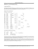
4.2 Output Log
Note
: Refer to Appendix 2 for the Log Report format.
This function is not applicable if Quantec’s ‘Surveyor’ mode is
active.
This function allows information stored in the Controller's
datalogger to be outputted to a standard Quantec RS232
printer (if connected). To execute, enter Access Level 2 or
Access Level 3 and Accept the 'Output Log' prompt. When
printing is complete, the Controller will return to the
previous menu. Please note, this function will only work if
the Controller's datalogger has been programmed to print
manually (refer to section 2.6) and a printer is properly
connected to its RS232 printing port.
4.3 Set Date
This function allows the date to be programmed into the
Controller. It is particularly important that the correct date is
entered if Quantec's datalogging function is to be used. To
execute, enter Access Level 2 or Access Level 3 and Accept
the 'Set Date' prompt. Use the scroll and Accept keys to select
the correct day, month and year. Pressing Accept after the
year has been entered will return you to the previous menu.
4.4 Set Time
This function allows the time to be programmed into the
Controller and is particularly important if Quantec's
datalogging function is used. To execute, enter Access Level
2 or Access Level 3 and Accept the 'Set Time' prompt. Use the
scroll and Accept keys to select the correct hour and minute.
When the minute data has been accepted you will be
returned to the previous menu.
4.5 Edit ID Texts
This function allows User/Caller ID names to be individually
edited at the panel.
Note
: After each User/Caller ID has been edited, the panel
automatically updates this ID on the system.
To execute, enter Access Level 2 and Accept the 'Edit ID Texts'
prompt. Use the scroll and accept keys to select and edit
names. Edit the ID names in the same manner as previously
described for custom texts (section 1.7).
4.6 Send ID Texts
This function globally sends User/Caller IDs from the panel.
Note: Only use this option, if say, a Display has been changed.
This process can take up to 2½ minutes to complete.
To execute, enter Access Level 2 and Accept the 'Send ID
Texts' prompt.
4.7 Network Reset
This function allows the network voltage to be reduced to
zero in order to reset all network devices. The Network is
powered down for approximately 5 seconds. To execute,
enter Access Level 2 or Access Level 3 and Accept the
'Network Reset' prompt.
Display Device
Waiting for Call
Set Day/Night
Mode is : Day
Set Day/Night
Mode is : Night
QT601-2 Quantec Controller
Installation & Programming Manual • Approved Document No. DNU6012001 Rev 5 • Page 25 of 42


