


QT601-2 Quantec Controller
Installation & Programming Manual • Approved Document No. DNU6012001 Rev 5 • Page 10 of 42
Planning an Installation
The
Quantec Controller
can be located anywhere on the
network, although it is normal practice to install it centrally
to reduce wiring runs, ideally in a manager or supervisor’s
office. If Quantec’s Surveyor data management software is
required, the PC used to run the software must be located
within 20 metres of the Controller.
Network Splitters
are best located in corridors where they can
be easily accessed. In addition to protecting the system from
open and short circuit faults, the more that are fitted, the
easier it is to install, commission and maintain the system.
As a general rule of thumb, install one splitter per corridor
junction (located at the end of the corridor nearest to the
Quantec Controller). However, if the corridor is longer than
50 metres, install the network splitter in the centre of the
corridor to reduce the wiring runs required for each limb.
Note that the
ONLY
recommended method of wiring Quantec
involves using network splitters.
DO NOT
wire any devices to
the spine other than network splitters. The more splitters you
use, the easier and quicker it is to program/fault-find.
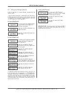
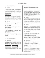
Refer to Splitter PCB layout drawing (below).
Each network splitter has:
• one input and one output network ‘spine’ connection
(both unfused).
• 6-fused (400mA) ‘limbs’ for wiring individual circuits
containing networked devices.
When wiring to a network splitter,
ALWAYS
remove the plug-
on connectors from the PCB and reconnect them when the
wiring is secure in the terminal block. Failure to so could result
in the terminal block twisting and the PCB being damaged.
Each splitter has two indicators, 'Power' indicates power is
being supplied to the network and 'Fault' indicates one of the
splitter’s circuits has a blown fuse. (N.B. unused circuits may
have their fuses removed without showing a fault).
No more than 60 addressable devices can be connected to
each network splitter.
General Purpose Wiring Instructions
With Quantec a limiting factor is voltage drop, which should
be limited to 5 volts worse case. As call points and overdoor
lights take different amounts of current depending on
whether they are in a calling or quiescent state, it is difficult
to predict the exact consequences of voltage drop without
knowing the exact configuration.
The System Wiring Overview on Pages 8 & 9 lists general rules
of thumb for wiring a Quantec system. In addition the
following is assumed:
1. Network splitters will be used throughout the network.
2. All spines will be wired in 1.5 mm
2
or 2.5 mm
2
c.s.a cable.
3. All limbs will be wired in 7/0.2 mm
2
strand cable. Use a
minimum of 4 core cable, doubling up by paralleling 2 cores
for the positive (NET+) and 2 cores for the 0 volt (NET-).
Don’t use single strand cable as it breaks too easily!
4. If Overdoor Lights are used, or devices are installed at the
end of a limb, use 6 core cable, twisted into 1 pair.
5. A maximum of 15 networked devices may be connected to
any limb, with the most distant device no further than 60
metres from the network splitter.
6. If possible, devices should be distributed at approximately
equal distances along the length of each limb.
First Fix
1. Plan cable routes and site the network splitters in
strategic positions as previously described. Please note, as the
system is addressable the programming of devices is not
dependent on their location on the network. Therefore,
devices that are difficult to access do not have to be
connected to the same network splitter as other call points in
the same area. For reference purposes, an example of the
planned cable routes for a fictional nursing home is shown
on Page 5.
Care should be taken when planning cable routes not to
exceed voltage drop limitations detailed above.
+ –
LIMB 1
+ – + –
+ – + – + –
+–
NET IN/OUT
+–
NET IN/OUT
NE
TW
OR
K RE
TTI
LP
S
F1
F2
F3
F4
F5
F6
LIMB 2
LIMB 3
LIMB 4
LIMB 5
2 CORE LIMB WIRING (minimum 4 core core security cable
twisted into one pair) into rooms and devices
/
2
/
2
/
2
/
2
/
2
/
2
/
2
/
2
2 CORE SPINE WIRING (e.g. 1.5 or 2.5 mm² T&E)
from Network Controller to other Network Splitters
LIMB 6
Quantec Network Splitter PCB Layout


