Appendix Connection Options with Inverters
Shenzhen BYD Electronic Co., LTD
56
HVS&HVM Operating Manual
q
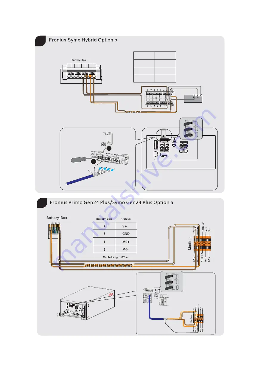
Shield
1
2
1 2 3 4 5 6 7 8
Battery-Box
5
6
8
7
+
-
D+
D-
Fronius
Fronius Smart Meter
Cable Length 20 m
≤
r
Page 1: ......
Page 2: ...t apply This document does not replace and is not intended to replace any local state provincial federal or national laws regulations or codes applicable to the installation electrical safety and use...
Page 3: ...TANT SAFETY INSTRUCTIONS 7 2 2 1 Battery Module Leakage 7 2 2 2 Firefighting Measures 8 2 2 3 Battery Modules Handling and Storage Guide 8 2 2 4 Warning of Electric Shock 9 2 2 5 Warning of Overvoltag...
Page 4: ...to an Inverter 26 6 4 1 Connection Options 26 6 4 2 Connecting the Data Cable of the Inverter 26 6 5 Connecting the Data Cable to other Battery System s 27 6 6 Connecting the Network Cables 30 6 7 DC...
Page 5: ...ystem Behavior under Fault Conditions 41 11 2 LED Light Designation for Errors 41 12 Maintenance and Storage 43 13 Disposal of the Battery System 44 14 Technical Data 45 15 Contact Information 47 Appe...
Page 6: ...em documentation including all safety instructions Training in dealing with the hazards associated with the installation and operation of electrical equipment and batteries Training in the installatio...
Page 7: ...VS HVM BCP Be Connect Plus BCU Battery Control Unit BIC Battery Information Collector BMS Battery Management System BMU Battery Management Unit BYD Shenzhen BYD Electronic Co LTD SOC State of Charge S...
Page 8: ...g changes or modifications are not allowed unless the written permission of BYD is achieved Unauthorized alterations will void the guarantee and warranty claims BYD shall not be held liable for any d...
Page 9: ...drag or step on the battery modules Do not insert unrelated objects into any part of the battery modules Do not throw the battery module into a fire Do not soak the battery modules in water or seawate...
Page 10: ...ages and if surge protection is missing Overvoltages e g in the event of a flash of lightning can be further conducted into the building and to other connected devices in the same network via the netw...
Page 11: ...ture penetration can damage the BCU and impair its functionality Only open the BCU if the humidity is within the thresholds and the environment is free of sand and dust NOTICE Damage to the battery sy...
Page 12: ...patible Inverter List Service Guideline and Checklist F Hanger wall part G Screw to fix D on BCU H Bolt to fix D and F J Screw to fix the connection between modules base and BCU x2 x2 x4 x2 D F G H Qu...
Page 13: ...storage of excess PV energy in an inverter system A BCU B Battery Module C Base D Operating Panel E LED Button F Air Switch There are two types of battery modules HVM and HVS The HVM module has two s...
Page 14: ...manual on how to connect up to three batteries The HVS system cannot be connected with the HVM system 4 2 Interface Be Connect 2 0 Be Connect 2 0 is an app for Android and iOS system devices You can...
Page 15: ...d diagnose the battery system and update firmware remotely for customers It is highly recommended you to make the Internet connection available to have a better service 4 3 Symbols on the System Symbo...
Page 16: ...cates that the system must be additionally grounded if additional grounding or equipotential bonding is required at the installation site Keep the battery modules away from children RCM Regulatory Com...
Page 17: ...ashing white quickly The battery system is discharging Flashing white and glowing blue The battery system is discharging and the SOC is below 15 Flashing white and blue An event message has occurred r...
Page 18: ...ion location must be inaccessible to children c The installation location must be suitable for the weight and dimensions of the battery system d The installation location must not be exposed to direct...
Page 19: ...n dealing with the battery system 5 1 4 Additionally Required Installation Material Pen Hair Dryer Wire Stripper Phillips Screwdriver Bit Flat Head Screwdriver Torque Wrench Tape Measure Wrench Cylind...
Page 20: ...attention to the direction of the module The blind mating connectors on the battery module and the base should be on the same side 6 Repeat the operations for other battery modules DANGER Danger to li...
Page 21: ...er wall part where it intends to be mounted on the wall and mark the position of the drill holes Please pay attention that there may be power cables or other supply lines e g gas or water routed in th...
Page 22: ...perating Manual 6 Electrical Connection 6 1 Overview of the Connection Area Exterior view a Gland for Ethernet cable b Gland for data cable s to connect to an inverter and another battery system c Gla...
Page 23: ...blocks for connecting an inverter s data cable CAN or RS485 protocol G RJ 45 port for connecting an inverter s data cable CAN protocol H I RJ 45 port for connecting with other tower s CAN protocol J...
Page 24: ...Shenzhen BYD Electronic Co LTD 6 Electrical Connection 23 HVS HVM Operating Manual 6 2 Connection Diagram 6 2 1 One Battery System INVERTER P P a c b d e Except for Kostal Piko MP plus...
Page 25: ...V DC c Maximum Output Current 40A DC d Breaking Current 40A DC 4 The total power cable length between each battery tower and the inverter should be less than 20 meters 1 1 Parallel connection is not a...
Page 26: ...ke off the nut of the cable gland 5 Take off the cable support sleeve inside of the cable gland 6 Get the PE inside of the cable support sleeve 7 Lead the PE through cable gland c 8 Strip the groundin...
Page 27: ...rements The cable length and quality affect the quality of the signal Observe the following cable requirements Cable category Cat5 Cat5e or higher Plug type Metal shielded RJ45 of Cat5 Cat5e or higher...
Page 28: ...arallel The following section and restrictions do not apply for the parallel connection with SMA Sunny Boy Storage 3 7 6 0 Please check the inverter operation manual on how to connect up to three batt...
Page 29: ...three battery systems could be read below Cat5 Cable Length 20 m Master Cat5 Parallel connection is not applicable to SMA Sunny Boy Storage 3 7 6 0 Please check the inverter Operating Manual on how t...
Page 30: ...ant for outdoor use Straight through wired cables Maximum cable length 20 m Procedure 1 Take off the nut of the cable gland b 2 Take the cable support sleeve inside of the cable gland 3 Take out the p...
Page 31: ...ces in the same network via the network cables or other data cables if there is no surge protection Touching live parts and cables results in death or lethal injuries due to electric shock Ensure that...
Page 32: ...ameter of the cable should be between 4 mm to 9 mm Follow the requirements of the inverter manufacturer Insulation stripping length 16 18 mm Maximum cable length 20 m Procedure 1 Take off the nut of t...
Page 33: ...and tighten the nuts on gland a and b with another hand 3 Fix the Operating Panel To do this insert the screws M4x14 through the holes on them using a Phillips screwdriver PH2 and tighten it torque 2...
Page 34: ...1 if available 2 2 2 1 Switch on the air switch between the battery and inverter if there is any 2 Open the plastic cover on the right side of the BCU 3 Push up the air switch from the Off position to...
Page 35: ...e is no Internet available you can press Skip to skip the firmware check 4 After the firmware downloaded press the button Check WIFI Settings to connect the battery WLAN which begins with BYD and the...
Page 36: ...urate before a full charge and discharge after the configuration CONFIGURATION BYD 069D Battery Box TIME INVERTER SYSTEM GRID Next xxxxxx 1 2 CONFIGURATION BYD 069D Battery Box Next TIME INVERTER SYST...
Page 37: ...Commission and configure the inverter according to the inverter manufacturer s instruction If the battery information could be read correctly it means the connection between the battery system and th...
Page 38: ...ystem The procedure to switch off the battery system is 1 switch off the inverter 2 switch off the battery 3 switch off the air switch between the battery and the inverter if there is any The correct...
Page 39: ...e battery system could support the black start function of compatible inverters The ways to trigger that are different for different inverters Please follow the inverter manufacturer s instructions he...
Page 40: ...1 Shut off the inverter 2 Switch off the battery system 3 Switch off the breaker between the inverter and the battery system if there is any 4 Take off the nuts on the cable glands on Operating Panel...
Page 41: ...sting system to an SOC of around 30 Note new modules have an SOC of around 30 2 Shut off the inverter 3 Switch off the battery system 4 Switch off the breaker between the inverter and the battery syst...
Page 42: ...sn t start at all please contact BYD local after sales service within 48 hours Otherwise the battery could be permanently damaged 11 Troubleshooting Please also see the BYD Battery Box Premium HVS HVM...
Page 43: ...ectronic Co LTD 42 HVS HVM Operating Manual Blue LED is flashing twelve times Inverter communication failure Blue LED is flashing thirteen times Address registration failed Blue LED is flashing fourte...
Page 44: ...C 50 C and charged regularly according to the table below with no more than 0 5 C A C rate is a measure of the rate at which a battery is discharged relative to its maximum capacity to the SOC of 30 a...
Page 45: ...posal regulations for electronic waste and used batteries Do not dispose of the battery system with your household waste Avoid exposing the batteries to high temperatures or direct sunlight Avoid expo...
Page 46: ...g 205 kg Battery designation IFpP 21 173 120 32S M 10 50 90 HVM 8 3 HVM 11 0 HVM 13 8 HVM 16 6 HVM 19 3 HVM 22 1 Battery Module HVM 2 76 kWh 51 2 V 38 kg Number of Modules 3 4 5 6 7 8 Usable Energy 1...
Page 47: ...closure Protection Rating IP55 Round trip Efficiency 96 Certification VDE2510 50 IEC62619 CEC CE UN38 3 Applications ON Grid ON Grid Backup OFF Grid Warranty 3 10 Years 1 DC Usable Energy test conditi...
Page 48: ...khurst NSW 221 www alpspower com au Europe EFT Systems GmbH service eft systems de Telephone 49 9352 8523999 44 0 2037695998 UK 34 91 060 22 67 ES 39 02 87368364 IT Address Bruchtannenstra e 28 63801...
Page 49: ...ing to the latest Battery Box Premium HVS HVM Compatible Inverter List before the installation a 4 3 1 2 1 2 3 4 5 6 7 8 A Parallel connection is not applicable to SMA Sunny Boy Storage 3 7 6 0 Please...
Page 50: ...B1 PVB2 BAT CAN DIG I O CAN DIG I O AC BACKUP AC GRID SMA STR5 0 10 0 SE Option a 1 2 3 4 SMA 1 3 4 2 BMS CAN DI DO 1 3 5 7 9 11 13 15 17 2 4 6 8 10 12 14 16 18 SMA Cable Length 20 m d Shield 1 2 SMA...
Page 51: ...BYD Electronic Co LTD 50 HVS HVM Operating Manual 1 2 3 4 5 6 7 8 Battery Box e 7 8 2 1 Battery Box KOSTAL 1 6 5 4 KOSTAL PLENTICORE Cable Length 20 m 1 2 3 4 5 6 7 8 f 5 6 7 8 Battery Box KOSTAL 1 6...
Page 52: ...ions with Inverters 51 HVS HVM Operating Manual g 5d 1 2 3 4 5 6 7 8 1 2 3 4 Battery Box KOSTAL Battery Box KOSTAL Smart Energy Meter Cable Length 20 m 6 2 1 2 3 4 5 6 7 8 1 2 6 5 Battery Box KOSTAL 5...
Page 53: ...c Co LTD 52 HVS HVM Operating Manual 1 2 3 4 5 6 7 8 Kaco blueplanet hybrid 6 0 10 0 TL3 Kaco 8 7 3 6 Battery Box Kaco SET BMS hy switch LAN Shield 1 2 i Cable Length 20 m 1 2 3 4 5 6 7 8 j 1 2 3 4 5...
Page 54: ...Appendix Connection Options with Inverters 53 HVS HVM Operating Manual k 4 5 1 2 Shield 1 2 GoodWe Viessmann Cable Length 20 m 1 2 3 4 5 6 7 8 l 1 2 3 4 5 6 7 8 H L 1 2 H L Battery Box Battery Box SUN...
Page 55: ...ating Manual m H L 1 2 H L Battery Box SUNGROW SUNGROW Shield 1 2 Cable Length 20 m 1 2 3 4 5 6 7 8 n Battery Box SUNGROW COM2 Meter R 485 S Enable A2 B2 A1 B1 EN_H H L A2 A2 RSD DO COM NO RJ45 CAN NC...
Page 56: ...NGROW COM2 Meter R 485 S Enable A2 B2 A1 B1 EN_H A2 A2 RSD DO COM NO RJ45 CAN NC EN_G NC NC L H NC L H 8 7 6 5 4 3 2 1 8 7 6 5 4 3 2 1 NC NC C R D4 8 D3 7 D2 6 D1 5 CAN H L 1 2 H L Battery Box SUNGROW...
Page 57: ...ppendix Connection Options with Inverters Shenzhen BYD Electronic Co LTD 56 HVS HVM Operating Manual q Shield 1 2 1 2 3 4 5 6 7 8 Battery Box 5 6 8 7 D D Fronius Fronius Smart Meter Cable Length 20 m...
Page 58: ...Shenzhen BYD Electronic Co LTD Appendix Connection Options with Inverters 57 HVS HVM Operating Manual t 1 2 3 4 5 6 7 8 1 2 CAN H CAN L Ingeteam Cable Length 20 m s...
Page 59: ...nection Options with Inverters Shenzhen BYD Electronic Co LTD 58 HVS HVM Operating Manual v 1 2 3 4 5 6 7 8 4 5 1 2 Solis Cable Length 20 m u 1 2 Shield 1 2 CAN H CAN L Ingeteam Cable Length 20 m 1 2...
Page 60: ...Shenzhen BYD Electronic Co LTD Appendix Connection Options with Inverters 59 HVS HVM Operating Manual w Shield 1 2 4 5 1 2 Solis Cable Length 20 m 1 2 3 4 5 6 7 8...