Page 50 of 61
INSTRUCTION, USE AND
MAINTENANCE MANUAL
EN
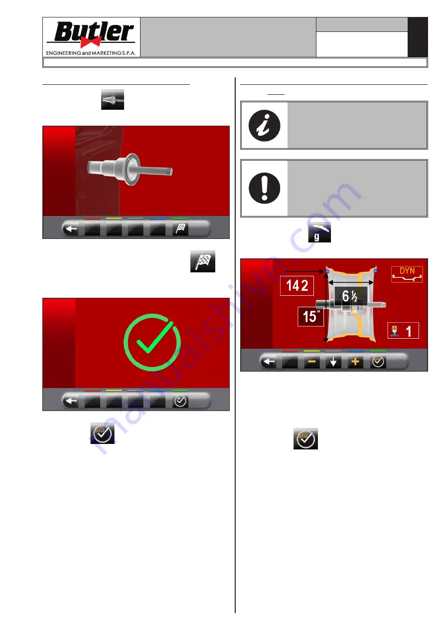
14.3.1 Chuck “0” (zero) calibration
Press the button
(
Fig. 44 ref. 1
) to display the
following screen page on the monitor:
After making sure that the chuck is unloaded (no wheel
or mounted accessories), press the button
and
close the guard. The chuck will rotate for a few minutes
until you see the screen below:
At this point the machine has all its measuring fields.
Press button
to return to calibrations screen
page.
14.3.2 Weight measurement sensors calibra-
tion
THE NUMERICAL VALUES SHOWN
IN THE FIGURES BELOW ARE
PURELY ILLUSTRATIVE.
ASSEMBLE A BALANCED WHEEL
ON THE SPINDLE AND PERFORM
THE CHUCK “0” (ZERO) CALIBRA-
TION PROCEDURE DESCRIBED
IN PAR. 14.3.1 (WITH WHEEL
MOUNTED).
- Press the button
(
Fig. 44 ref. 2
) to display
the following screen page on the monitor:
- Set the size of the rim on the chuck using the dis-
tance-diameter caliper arm.
- Set the rim width using one of the following calipers:
• Manual caliper
• External data gauge (optional)
- Press button
and close the guard to the per-
form the 1st spin of the wheel without weights.
- At the end, on the monitor will appear the following
screen, saying that you should apply a weight of 100
g (3.52 oz) to the “12 o'clock” outer rim.
1296-M024-01
LIBRAK350 - LIBRAK350PRO


