background image

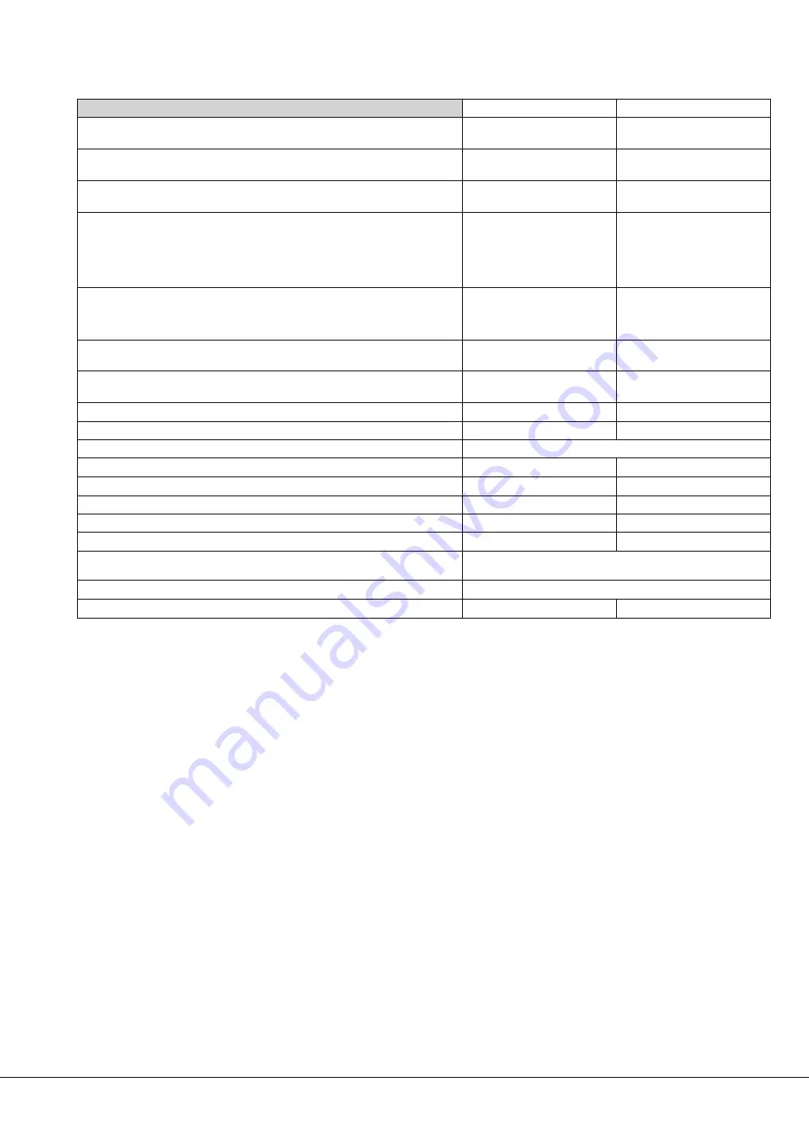
Technical Data

Technical data

NS 0070 C

NS 0160 C

Nominal suction capacity

50 Hz
60 Hz

m

3

/h (cfm)

m

3

/h (cfm)

70 (41)
85 (50)

135 (79)
160 (94)

Ultimate pressure

Torr

mbar

2,2 x 10

-2

3,0 x 10

-2

2,2 x 10

-2

3,0 x 10

-2

Nominal motor rating

50 Hz
60 Hz

kW
kW

4,0
4,4

5,5
6,6

Motor voltage and

current rating

50 Hz

D

200 V

D

230 V

D

255 V

Y 346 V

Y 400 V

Y 440 V

A

A

A

A

A

A

15.9

16.6

20

9.2

9.5

11.7

21

20.5

25

12.2

11.7

14.3

Motor voltage and

current rating

60 Hz

D

200 V

D

277 V

Y 346 V

Y 480 V

A

A

A

A

17.2

15.8

9.9

9.1

27

21

15.4

12.0

Nominal motor speed

50 Hz
60 Hz

min

-1

min

-1

3000
3600

3000
3600

Noise level (EN ISO 2151)

50 Hz
60 Hz

dB(A)
dB(A)

62

68

Ambient temperature

°C (°F)

0-40 (32-104)

0-40 (32-104)

Maximal counter pressure

Discharge

bar

0,2

0,2

Maximum inlet pressure

Atmospheric pressure

Cooling water temperature

°C (°F)

10 - 30 (50 - 86)

10 - 30 (50 - 86)

Cooling water requirement

l/ min

³

3

³

3

Cooling water pressure

bar

3 -6

3 -6

Nitrogen requirement

approx.

slm

0 - 18

0 - 18

Nitrogen overpressure

bar

1,5

1,5

Maximal allowed

operationnal speed

Refer to nameplate

Leakrate

mbar x l/s

£

1 x 10

-6

Weight

approx.

kg

250

250

NS 0070-0160 C

Technical Data

0870570353 (En)

Page 21

Summary of Contents for COBRA NS 0070-0160 C

Page 1: ...allation and Maintenance Instructions Screw Vacuum Pumps COBRA NS 0070 0160 C Ateliers Busch S A Zone industrielle 2906 Chevenez Switzerland 0870570353 181017 Original instructions Modifications reser...

Page 2: ...d oil 14 Filling in new oil 14 Checking the cooling liquid 14 Checking the level of the cooling liquid 14 Refilling cooling liquid 14 Filling in cooling liquid 14 Draining the cooling liquid 14 Checki...

Page 3: ...water flow meter OFP Oil filler plug OSG Oil sight glass ODP Oil drain plug GC Nitrogen connection option DGR Nitrogen regulating valve option FIS 02 Nitrogen flow meter option PMR Unblocking screw fo...

Page 4: ...be combined with a Busch booster pump i e type WY 0500 C Cooling The vacuum pump is cooled by a cooling water circuit in the cylinder 4 indirect cooling A temperature probe mounted in the cylinder of...

Page 5: ...cognise these instructions by the signal words DANGER WARNING and CAUTION which are defined as follows DANGER Disregard of this safety instruction will always result in death serious injuries or sever...

Page 6: ...kaging can attack synthetic surfaces and surfaces of other elastomers If in doubt please contact your nearest distributor VCI packaging provides several years of protection against corrosion even unde...

Page 7: ...or solid particles can lead to the destruction of the vacuum pump If the sucked gas contains dusts or solid foreign bodies u Make sure that a suitable filter or protective screen is installed at the...

Page 8: ...doubts contact your Busch representative Installation Assembly l Make sure that the necessary installation instructions are followed l Fasten or install the pump at its final installation site Electr...

Page 9: ...stopping of the vacuum pump when the flow drops below 2 l min The cooling water flow is factory set on 2 5 l min and can be adjusted at the regulating valve CWR This water circuit is used to cool the...

Page 10: ...s l Stop the vacuum pump and wait a few minutes l Make sure that the oil level still lies between the MIN and MAX markings on the oil sight glasses If the oil level is below the MIN marking u Fill in...

Page 11: ...een atmospheric and ultimate pressure CAUTION The surface temperature of the vacuum pump can exceed 70 C when the vacuum pump is in operation Risk of burns The vacuum pump may not be touched when it i...

Page 12: ...off the nitrogen supply l Shut off the cooling water supply Maintenance DANGER In case the vacuum pump has conveyed gases that have been contaminated with foreign materials that are dangerous to heal...

Page 13: ...t the water outlet CWo and then the water inlet CWi and nitrogen connection GC l Switch on the main power supply l Make sure that the Installation prerequisites are followed l Switch on the vacuum pum...

Page 14: ...e oil level lies between the MIN and MAX markings on the oil sight glasses l Make sure that the seals of the filler cap are not damaged and that they sit properly Replace them if necessary l Screw on...

Page 15: ...a danger to the environment Prior to shipping the vacuum pump must imperatively be decontaminated and the degree of contamination must be documented in a declaration of decontamination Declaration of...

Page 16: ...ion regulations Begin dismantling the vacuum pump CAUTION Wear protective clothing when carrying out dismantling work u Dispose of the vacuum pump as scrap metal Dispose of the individual parts of the...

Page 17: ...d protection is too small or trip level is too low Compare the trip level of the drive motor starter overload protection with the data on the name plate Correct if necessary In case of high ambient te...

Page 18: ...uit and adjust the flow if necessary Ambient temperature too high Observe the permitted ambient temperatures Temperature of the inlet gas too high Observe the permitted temperatures for the inlet gas...

Page 19: ...hemically contaminated or polluted oil can lead to hazardous pump conditions which could cause personal injury Oil quantity The quantity of oil specified in the following table is of informative natur...

Page 20: ...f informative nature only Respect the procedure of filling the cooling liquid Quantity Zitrec M 25 already mixed ready to use NS 0070 0160 C 4 litres CAUTION The proportion of pure glycol and water fo...

Page 21: ...V Y 480 V A A A A 17 2 15 8 9 9 9 1 27 21 15 4 12 0 Nominal motor speed 50 Hz 60 Hz min 1 min 1 3000 3600 3000 3600 Noise level EN ISO 2151 50 Hz 60 Hz dB A dB A 62 68 Ambient temperature C F 0 40 32...

Page 22: ...g the standards Standard Title of the standard EN ISO 12100 2010 Safety of machinery Basic concepts general principles of design EN ISO 13857 2008 Safety of machinery Safety distances to prevent hazar...

Page 23: ...Note...

Page 24: ...myun Icheon si Gyunggi do 467 813 Republic of Korea Phone 82 31 645 2700 Fax 82 31 631 2898 e mail busch busch co kr Malaysia Busch Malaysia Sdn Bhd 4 6 Jalan Taboh 33 22 Seksyen 33 Shah Alam Technolo...

Reviews: